Do you have a question about the Mutable Instruments Veils and is the answer not in the manual?
Description of VCAs as building blocks and how Veils provides four VCAs with adjustable response and daisy-chained outputs.
Details Veils' power supply needs (-12V/+12V) and LED brightness dependency on current consumption.
Explains the continuously variable response curve (A) and the positive offset control (B) for CV signals.
Details the Gain CV amount control (C) and the normalized Gain CV input (2) for modulation.
Describes the DC-coupled signal input (3) and the daisy-chained signal output (5) with sum functionality.
Explains the Gain indicator LED (1) and the Output indicator LED (4) and their function.
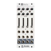
The Mutable Instruments Veils is a Quad VCA (Voltage Controlled Amplifier) module designed for modular synthesis systems. VCAs are fundamental components in modular patches, serving various purposes such as shaping the amplitude of sounds with envelopes, animating mixtures of oscillators, adjusting filter modulation with random sources or touch plates, and controlling the amount of FM applied to an oscillator. Veils offers four independent VCAs, each with adjustable parameters, making it a versatile building block for complex sound design and modulation.
The primary function of Veils is to provide four VCAs that can control the amplitude of audio or CV signals. Each VCA features an adjustable response curve, an offset control, and a gain CV amount control. The module's outputs are daisy-chained, allowing for convenient mixing of adjacent channels in groups of 2, 3, or all 4, without the need for external mixers.
Each of the four VCA channels on Veils offers several controls and indicators:
| Brand | Mutable Instruments |
|---|---|
| Model | Veils |
| Category | Synthesizer |
| Language | English |