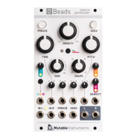
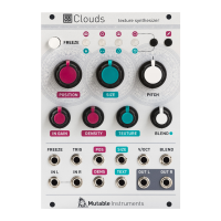
Resonator section
Controls
A. COARSE and FINE frequency controls. They control
the fundamental frequency of the resonator’s frequency
response. COARSE is quantized by semitone increments.
B. Attenuverter for the FM CV input.
C. Instrument GEOMETRY. This parameter adjusts the
frequencies, gains, and Q-factors of the resonator’s fi l-
ters in order to simulate various structures and materi-
als. As you rotate this knob, you’ll fi nd:
Plates (metal)
Strings (steel, nylon)
Bars and tubes (glass, wood)
Bowls (glass, metal)
D. BRIGHTNESS. Controls the damping of high frequen-
cies. Low values of this parameter simulate materials
like wood or nylon. High values simulate materials like
glass or steel.
E. DAMPING controls how quickly energy dissipates
through the material. Modulating this parameter by CV
can recreate the effect of damping or muting the sound
by blocking the vibrating surface with the hand.
F. POSITION controls on which point of the structure the
excitation is applied. Applying the excitation right in the
middle of the surface will cause even harmonics to can-
cel each other, resulting in a hollow sound reminiscent
of a square wave. POSITION is nature’s PWM/phaser
effect!
G. SPACE. Stereo control and reverberation.
When this knob is set to its minimum position, the left
channel contains the exciter output, and the right chan-
nel the resonator signal - for further external mixing.
As SPACE increases, a stereo effect is created by picking
up the vibrating surface’s sound at two different posi-
tions. Past 12 o’clock, SPACE controls the amount and
decay time of an algorithmic reverberator applied to the
resonator signal.
H. Attenuverters for the CV inputs.
Inputs and outputs
1. CV inputs for the fi ve resonator parameters.
Tips and Tricks
The resonator can behave like a formant fi lter. Feed a
sawtooth or narrow PWM signal to one of the external
inputs, set BRIGHTNESS to a low value, DAMPING to a
low value, and modulate GEOMETRY to go through var-
ious confi gurations of formants. Then sweep the main
frequency.
A very high CV on the SPACE CV input causes the reverb
to have an infi nite decay (freeze effect).
A B
C D
E
F
G
H
1
Elements
Modal synthesizer
Please refer to the online manual for detailed infor-
mation regarding compliance with EMC directives