Do you have a question about the Mutec REF10 SE120 and is the answer not in the manual?
General guidelines for reducing fire or electrical shock risks and ensuring proper airflow.
Instructions for inspecting the unit before initial use and handling condensation.
Details on the self-adapting power supply and grounding requirements.
Disclaimer regarding manual information and product names.
Statement of compliance with European standards on electromagnetic compatibility.
Covers the two-year warranty period and MUTEC's repair/replacement policy.
Explains that the warranty is non-transferable to subsequent owners.
Outlines the process for warranty claims and product return.
Lists conditions that are not covered by the warranty.
Provides instructions on how to obtain warranty service and contact MUTEC.
Overview of the REF10/REF10 SE120 as an audiophile 10 MHz reference master clock generator.
Lists key features of both the REF10 and REF10 SE120 models.
Details specific enhanced features of the REF10 SE120 model.
Lists the items included in the REF10/REF10 SE120 package.
Guidance on optimal placement of the unit to avoid vibration and ensure ventilation.
Explains the 50 Ω and 75 Ω impedance standards for clock signals.
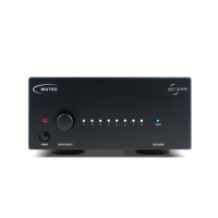
Description of the controls and indicators on the front of the device.
Description of the connections and switches on the rear of the device.
Step-by-step guide on how to operate the REF10/REF10 SE120.
Advice for optimal performance, including burn-in and placement.
Illustrates various applications and how to achieve best sonic results.
Instructions on how to adjust the line voltage setting for the device.
Lists specifications for interfaces, signal format, and clock generation.
| Output Frequency | 10 MHz |
|---|---|
| Output Impedance | 50 Ohms |
| Number of Outputs | 8 |
| Power Supply | 100-240 V AC, 50/60 Hz |
| Output Connectors | BNC |
| Category | Master Clock |
| Power Consumption | 25 W max. |
| Type | Reference Clock |