REF 10
16
Appendix
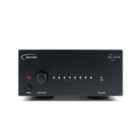
Changing the Line Voltage
Always unplug the mains cable before changing the line
voltage fuse!
On the left hand side of the mains power module on the rear
you will see two small triangles facing each other (see left
arrow in picture above). The respective line voltage »110-120
V« or »220-240 V« is printed above the right triangle. If this
setting should not be appropriate for your power grid, the fuse
holder (see right arrow in picture above) needs to be pulled
out, rotated by 180° around its own axis, and be put back in
place. You should then see that the triangle now indicates the
correct line voltage. It is easiest to remove the fuse holder by
inserting a small flat screwdriver in the groove on the right
side of the fuse holder to pull it outwards.
Make sure that the fuse holder is properly seated in its
housing with its top flush to the power!
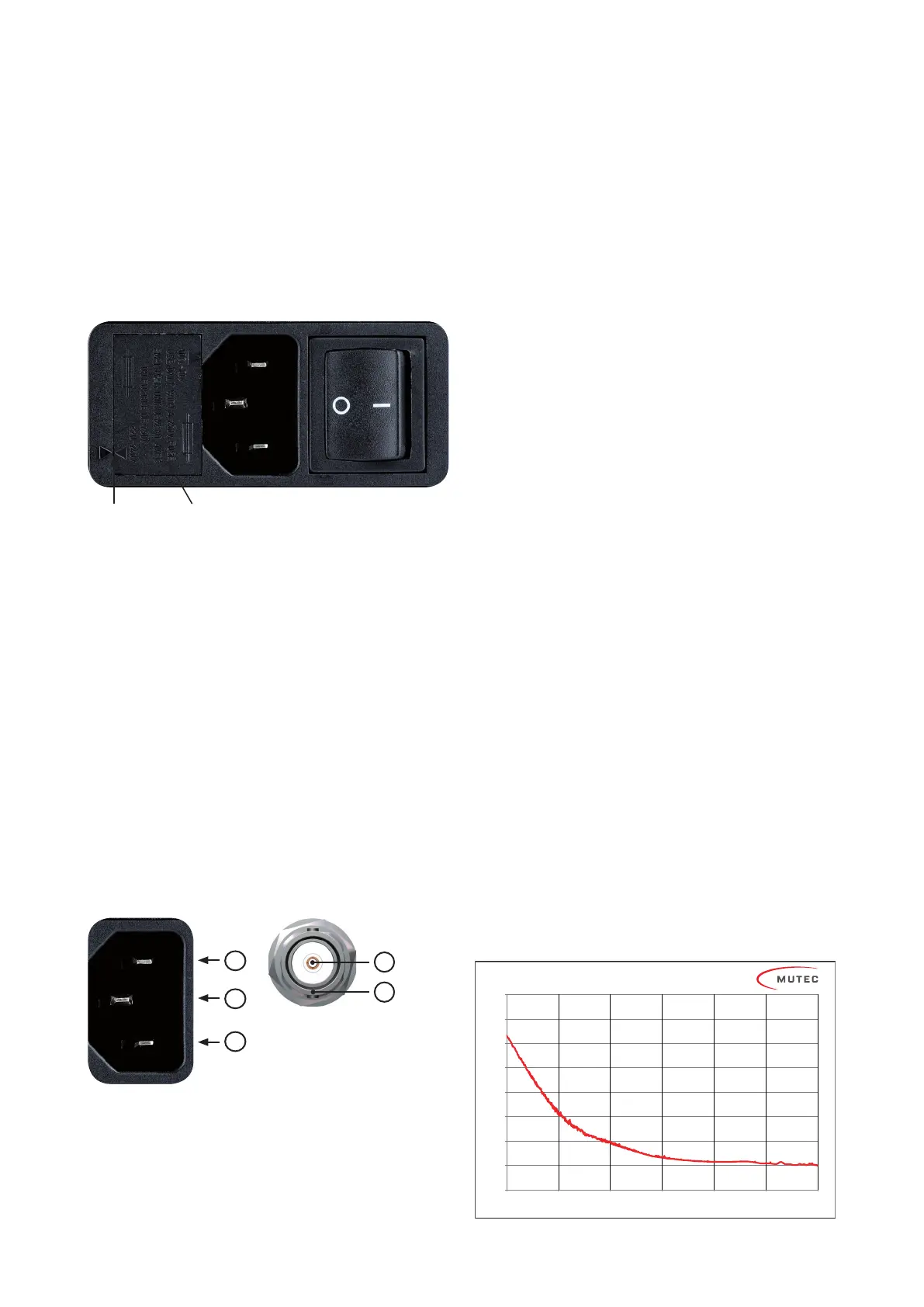
Pin Assignment of the Terminals
Mains In
1) Neutral (N)
2) Protective Earth (E)
3) Live, Phase (P)
Technical Data
Interfaces:
•
2 x BNC, unbalanced, 50 terminated, galvanically
isolated, buffert
•
6 x BNC, unbalanced, 75 terminated, galvanically
isolated, buffert
Signal format of all clock outputs
•
Square wave, 10.000 MHz, 2 Vpp, 50:50 duty cycle
Clock Generation:
•
Type: 10.000 MHz ultra-low phase noise oven-controlled
crystal oscillator
•
Frequency accuracy when shipped: < ±0.01 ppm
•
Frequency stability vs. temperature range: < ±0.01 ppm
within -20 °C to +70 °C (-4 °F to +158 °F)
•
Short term stability (Allan Deviation, typically Tau = 1s):
REF10: 1 × 10
-12
REF10 SE120: 2.5 × 10
-13
•
Aging after 30 days operation: : < +/-0.0002 ppm (per
day), < +/-0.03 ppm (first year), < +/-0.2 ppm (ten years)
•
Warm-up time at +25 °C (+77 °F): <5 min
Phase noise measured at REF10's outputs (!):
•
1 Hz: ≤ -116 dB/c
•
10 Hz: ≤ -145 dB/c
•
100 Hz: ≤ -160 dB/c
•
1000 Hz: ≤ -166 dB/c
•
Noise Floor: ≤ -170 dB/c
(Disclaimer: All measurement figures represent average values. Minor
production related deviations will be expected.)
Fuse HolderTriangles
1
2
3
BNC-Ausgang 50/75 Ω
1) Signal
2) Ground
1
2
-180
-170
-160
-150
-140
-130
-120
-110
-100
1 10 100 1.000 10.000 100.000 1.000.000
dBc/Hz
Hz
Ref 10 Phase Noise
REF 10 Phase Noise
dBc/Hz
Hz