- 24 -
Electrical system
E
A – with neutral engaged, the contact is closed.
B – for ECU with “Pull up” input to battery voltage or for
negative coil ignition feed relay.
C – side stand switch.
D – Neutral warning light.
E – Side stand lowered warning light position.
F – Clutch switch.
G – 1N5404 diode.
H – Engine start switch.
CPU
The CPU includes a group of functions previously performed by other components of the motorcycle. This allowed
to simplify wiring and to reduce connections. The general reliability of the unit is enhanced and overall weight is
reduced.
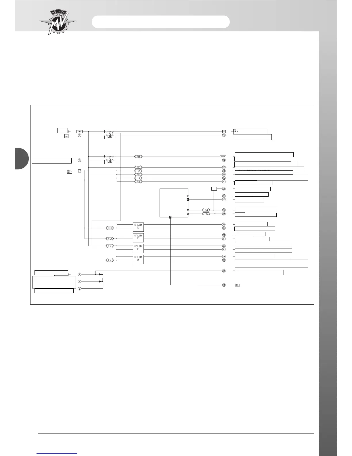
FUNCTION DIAGRAM
BAT
ON/OFF RIGHT CONTROL
CLUTCH SWITCH
ENGINE CONTROL GERCASE
PIN 7
CLUTCH SWITCH
STAND SWITCH
NEUTRAL SWITCH
IGNITION SWITCH
FUEL-INJECTOR-COIL PUMP
ENGINE CONTROL GEARCASE PIN 23
DIRECT POSITIVE FOR INSTRUMENT PANEL
ALTERNATOR – TAIL LIGHTS
RIGHT CONTROL – KLAXON POSITIVE 02
STOP LIGHTS POSITIVE 04
INTERMITTENCE LED
RIGHT IND. CONTROL
LEFT IND. CONTROL
RIGHT TURN INDICATORS
LEFT TURN INDICATORS
DRIVING BEAM
DRIVING BEAM CONTROL
LOWER BEAM
LOWER BEAM CONTROL
ENGINE CONTROL GEARCASE PIN 35
ENGINE CONTROL GEARCASE PIN 4
ELECTRIC FAN
ELECTRIC FAN CONTROL FROM ENGINE CONTROL
GEARCASE
REMOTE CONTROL SWITCH COIL
ALTERNATOR – SPEED SENSOR –INSTRUMENT PANEL – RESERVE
PROBE POSITIVE 03
ELECTRICAL SYSTEM









 To Next Page