8
2A3 – MODELS WITH GRAVITY DRAINAGE
N.B.
The drainage line must comprise of a free
flow sump pit of the proper size capable
of disposing twice the water flow as
indicated on the data diagram. It must be
close to the drain pipe of the
machine without bending, stretching or
joining the pipe.
- Drain line must reach sump pit free
flowing without constraints, stretching,
bends, kinks, or being forced.
- Connect the waste outlet pipe to the main
drain pipe, fitting a trap, or place the
outlet pipe over an “S” trap set into the
floor.
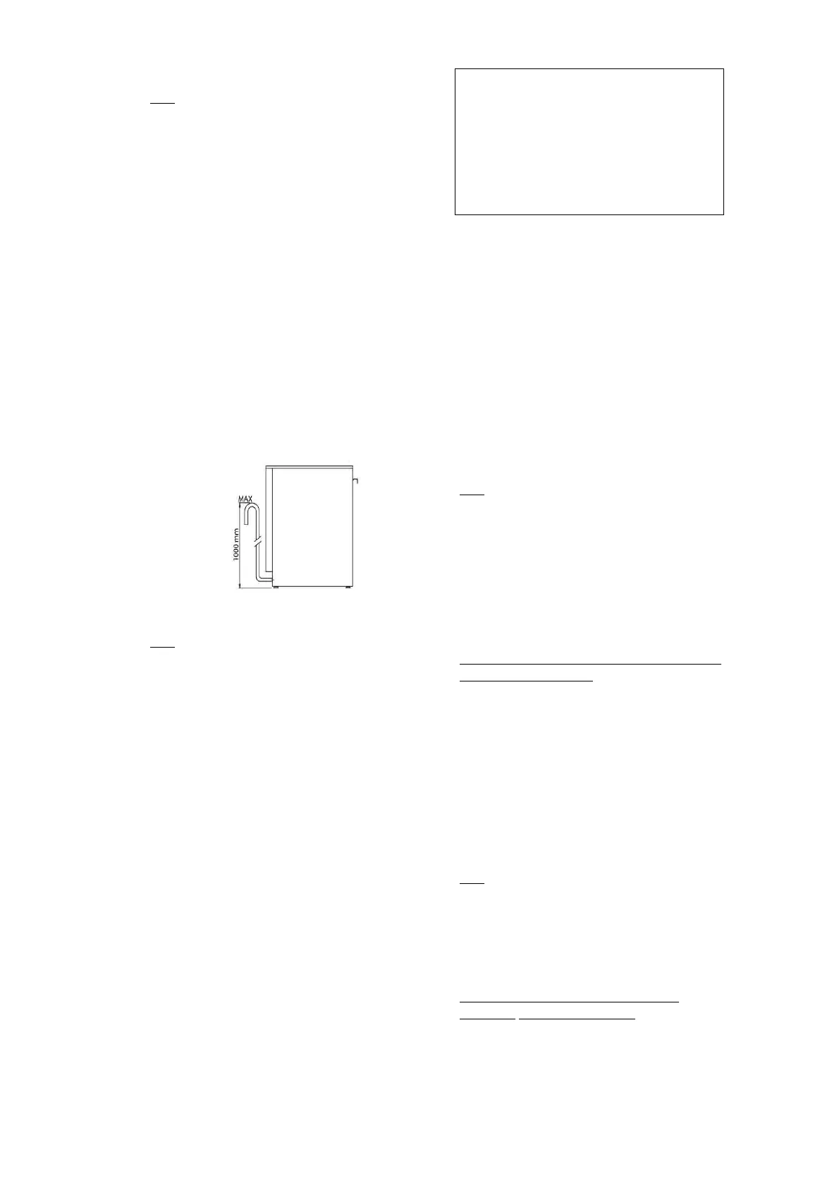
2A4 – MODELS WITH DRAIN PUMP
- Position the outlet pipe at a height
anywhere between 30” and 40” from the
floor. (Fig.6)
Fig. 6
2B - ELECTRICAL CONNECTION
N.B.
All contacts must be mechanically
open, with a ground line included,
min. distance between contacts 3 mm,
with magnetic overload or fuses,
calibrated for a max, sustained current
in agreement with machine data
plate. It must be installed outside the
machine but close to it. It must feed only
one machine at time.
Machine cannot be connected to the
mains using adapters, plug, cables or
cable extensions not properly sized
and must be adequate for the
machine’s power requirements.
- Verify main specifications comply with
indicated requirements on the data plate
located on the front bottom panel of the
machine (par. ID/RATING/DATA PLATE), that
exists for the connection, a main breaker
with proper size suitable for the machine
and a proper ground system.
The line cable should be replaced with a spare
cable supplied by the manufacturer. For
replacement indicate machine type, machine
serial number and possible installation
modifications. The power cable must not be
stretched or kinked during normal operation.
Grounding point on machine must
be connected to the nearest appliance
terminal according to Safety Standards.
2C – WARNING MESSAGES
DISPLAYED ON THE CONTROL
PANEL
N.B.
If the machine is in OFF mode, warning
messages will not be displayed. Turn ON
the machine to be able to visualize the
warning message on the appliance.
Following warning messages on the display
are provided:
ALR1 - WATER FILL
Water fill not completed during the available
maximum time (10min).
Verify that water supply is correctly
connected, open and free of obstructions.
Verify that solenoid valve filter is free
of possible obstructions and deposits. Verify
that water supply pressure is adequate (par.1D
– Technical Data).
Verify that machine’s door is completely
closed and the overflow device is correctly
positioned inside the tank.
N.B.
If water fill timing expires, the solenoid
valve is automatically interrupted. To
restart solenoid valve press any button on
the control panel.
ALR2 - DRAIN ANOMALY
Drainage not completed during the
maximum programmed timing.
The manufacturer is not responsible for
injuries caused by improper grounding.
The electrical connection must be in
compliance with the national regulations
 Loading...