North American Clutch & Driveline
Rockford, Illinois
Phone: (800) 383-9204
(815) 282-7960
Fax (815) 282-9160
www.naclutch.com
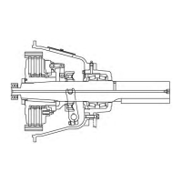
Figure 3: Checking Drive Ring Surface of Flywheel
7.
8.
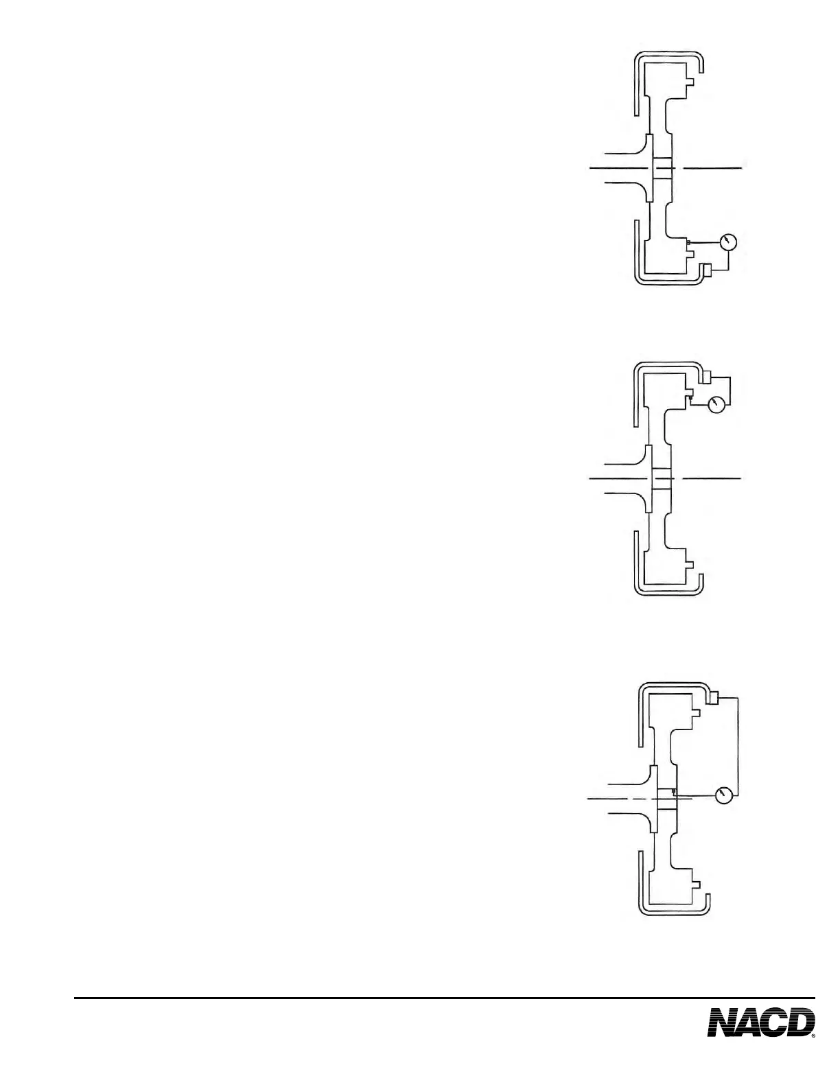
Figure 4: Checking Drive Ring Pilot Bore of Flywheel
9.
10.
Figure 5: Checking Pilot Bearing Bore of Flywheel
11.
Rotate the shaft through one entire revolution
and note the face run out of the ywheel. The
total indicator reading must not exceed .0005"
.01 mm) per inch (25.4 mm) of ywheel diameter.
Apply thrust onto crankshaft in one direction to
prevent crankshaft end play from affecting run
out measurement.
Readjust the indicator stem so it rides on the
driving ring pilot bore of the ywheel. See
Figure 4.
Rotate the shaft through one entire revolution
and note the driving ring bore eccentricity. The
total indicator reading must not exceed .005"
(.13 mm).
Adjust the indicator stem so that it rides on
the pilot bearing bore cavity. See Figure 5.
Rotate the shaft through one entire revolution
and note the pilot bearing bore eccentricity. The
total indicator reading must not exceed .005"
(.13 mm).
Figure 3
Figure 4
Figure 5
7