North American Clutch & Driveline
Rockford, Illinois
Phone: (800) 383-9204
(815) 282-7960
Fax (815) 282-9160
www.naclutch.com
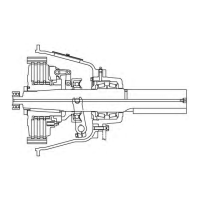
Power Take-Off Installation to Engine or Driving Member
1.
2.
3.
4.
5.
Engine and/or power take-off failure will result form any excessive preload
on components.
6.
Clean the power take-off housing ange, ywheel housing ange, and pilot bearing
bore or any debris. Install two alignment studs into the ywheel housing to assist
with the power take-off installation.
Install 2 or 3 guide studs in the ywheel housing. Position the power take-off against
the ywheel housing, carefully aligning the main shaft pilot with the pilot bearing bore
and the driving plates with the drive ring.
Secure the power take-off housing to the ywheel housing with 12 hex-head cap-
screws. Torque the capscrews to the proper specications given in Torque Values
for Fasteners.
Note: Power take-off housing to ywheel housing attachment screws must be grade
5 or better.
Rap the output end of the clutch shaft with a soft hammer to remove any preload on
the main bearings and/or pilot bearing.
Note: This step must not be omitted. Bearing failure may result.
Measure the crankshaft end play again. The measurement must be the same exact
value as recorded from Step 1 under Preliminary Checks. Locate and correct the
source or preload if the end play is not the same value.
Install the key on the output shaft and install the drive sheave, chain sprocket, or u-
joint ange as the application requires.
Note: A power take-off support plate mounted at the output bearing retainer is con-
sidered mandatory for this unit.
9