Do you have a question about the NAD 3120 and is the answer not in the manual?
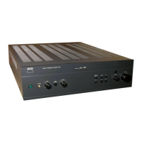
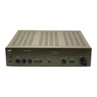
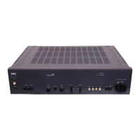
Details connections on the rear of the amplifiers.
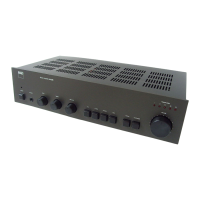
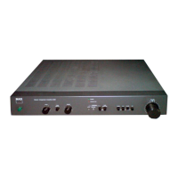
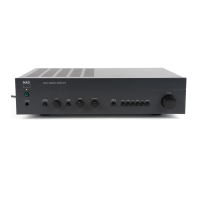
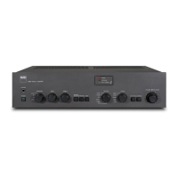
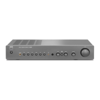
Identifies front panel controls for both amplifier models.
Details specifications for the power amplifier stage.
Details specifications for the preamplifier stage.
Provides physical dimensions and weight details.
Visual representation of the amplifier's internal components.
Schematic representation of the signal flow and functional blocks.
Procedure for checking and adjusting the idle current.
Procedure for checking and adjusting the DC offset.
This document serves as a service manual for the NAD 3020B and 3120 Integrated Stereo Amplifiers, providing comprehensive information for maintenance, repair, and understanding of the devices.
The NAD 3020B and 3120 are integrated stereo amplifiers designed to deliver high-quality audio reproduction. Their primary function is to amplify audio signals from various sources and drive loudspeakers, providing a complete audio solution for home entertainment systems. These amplifiers are built with a focus on sound quality and user flexibility, offering a range of input options and control features to tailor the listening experience.
At its core, the amplifier takes low-level audio signals from source components and boosts them to a level sufficient to power loudspeakers. The "integrated" aspect means that both the preamplifier and power amplifier sections are housed within a single chassis, simplifying the setup and operation for the user.
The preamplifier section handles input selection, volume control, and tone adjustments. It features multiple input options to accommodate various audio sources, including a dedicated phono input for turntables, tuner input for radio receivers, and auxiliary (AUX) inputs for other line-level devices like CD players or cassette decks. The phono input is particularly versatile, offering a selectable MM/MC (Moving Magnet/Moving Coil) switch to accommodate different types of phono cartridges, which is a significant feature for vinyl enthusiasts. This allows for optimal impedance matching and gain for a wide range of turntables. A tape play/record loop is also included, enabling connection of a cassette deck or other recording device for both playback and recording functions.
The power amplifier section is responsible for the final amplification stage, delivering the necessary current and voltage to drive loudspeakers. These amplifiers are designed to handle a range of speaker impedances, with a "Soft Clipping" feature that helps prevent harsh distortion when the amplifier is driven beyond its rated output, ensuring a more musical sound even at high volumes. This is a user-friendly feature that protects both the amplifier and speakers from potential damage due to excessive clipping. The rear panel also includes AC convenience outlets, allowing other audio components to be powered directly from the amplifier, simplifying cable management.
The front panel controls are intuitively laid out for ease of use. A prominent volume knob allows for precise adjustment of the overall listening level. Separate bass and treble controls provide tone adjustment, enabling users to fine-tune the frequency response to their preference or to compensate for room acoustics. A balance control allows for adjustment of the relative volume between the left and right channels, useful for correcting imbalances in speaker placement or source material.
Input selection is managed through a rotary switch or dedicated buttons, allowing users to easily switch between phono, tuner, AUX, and tape sources. A mono switch is available for playing mono recordings or for troubleshooting channel balance issues. The "Loudness" contour feature compensates for the ear's reduced sensitivity to bass and treble frequencies at low listening levels, providing a fuller sound at quiet volumes.
For private listening, a headphone jack is conveniently located on the front panel, allowing users to enjoy their music without disturbing others. The 3020B model also includes an LED power meter, which provides a visual indication of the output power, offering a dynamic display of the amplifier's operation. The rear panel offers "Pre-Amp Out" and "Normal In" connections, which allow the preamplifier and power amplifier sections to be used independently. This is a valuable feature for users who wish to integrate an external power amplifier, an equalizer, or other signal processing equipment into their system. A "Lab In" connection might also be present, potentially offering a direct input to the power amplifier stage, bypassing the preamplifier for specific applications or testing.
The service manual provides detailed instructions for maintenance and troubleshooting, making it a valuable resource for qualified service personnel. Key maintenance features include:
In summary, the NAD 3020B and 3120 Integrated Stereo Amplifiers are designed for robust audio performance and user-friendly operation, with comprehensive service documentation to support their long-term maintenance and repair.
| Frequency Response | 20Hz to 20kHz |
|---|---|
| Dimensions | 420 x 96 x 240 mm |
| Damping Factor | 50 |
| Type | Stereo Integrated Amplifier |
| Power Output | 20 watts per channel into 8Ω (stereo) |
| Total Harmonic Distortion | 0.03% (at rated power) |
| Input Sensitivity | 2.5mV (MM) |