Do you have a question about the NAD 3400 and is the answer not in the manual?
Details on all rear panel input/output and control connections.
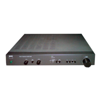
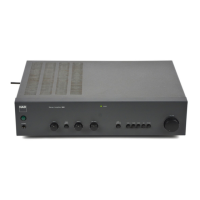
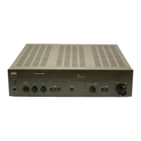
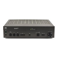
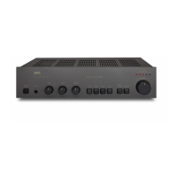
Explanation of all front panel knobs, switches, and indicators.
Technical details for the power amplifier stage, including output power and distortion.
Technical details for the amplifier operating in bridged monophonic mode.
Description of Treble, Bass, EQ, Infrasonic Filter, and Audio Muting functions.
Dimensions, weight, and power consumption details of the amplifier.
Steps for checking center voltage and adjusting idle current in the main amplifier.
Procedure for adjusting channel balance for the preamplifier stage.
Layout diagram for the input/output printed circuit board assembly.
Layout diagram for the main, control, and supply printed circuit board assembly.
Layouts for mains input, headphone, power, and bridge switch assemblies.
Layout diagram for the selector printed circuit board assembly.
Layout diagram for the µCOM (microcontroller) printed circuit board assembly.
Layout diagram for the tactile switch printed circuit board assembly.
Diagram illustrating the wiring connections between major internal assemblies and external components.
Detailed list of parts shown in the exploded view diagram with part numbers.
List of electrical components for the main, control, and supply PCB assembly.
List of electrical components for the input/output PCB assembly.
List of electrical components for the selector PCB assembly.