“4” corresponds to the pre-selections
area. The corresponding led will turn
green.
“5” is the ambient light level detector.
When the LED’s are in the AMBIENT
mode (CORRECTION: AMBIENT),
the brightness of the LED’s will be
adapted to the ambient lightning.
“6” is the infrared receiver for the
remote control.
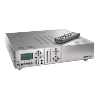
1.2 FRONT OUTPUT PANEL
The left part (FRONT L & R) shows the
modulometers indicating the output level
of the FRONT channels.
The way the LED’s are lighting up can be
selected in the LED sub menu.
The cross indicates the physical position
of the adjustment potentiometers. The
vertical LED’s are showing the position of
the output volume potentiometer where
the horizontal LED’s are showing the
position of the balance potentiometer. Be
aware that if the balance is in the middle
position, the middle LED is not lighting.
The lower right corner shows the arrow keys permitting the adjustment of the output
level (up or down arrow keys) and the balance (left or right arrow keys).
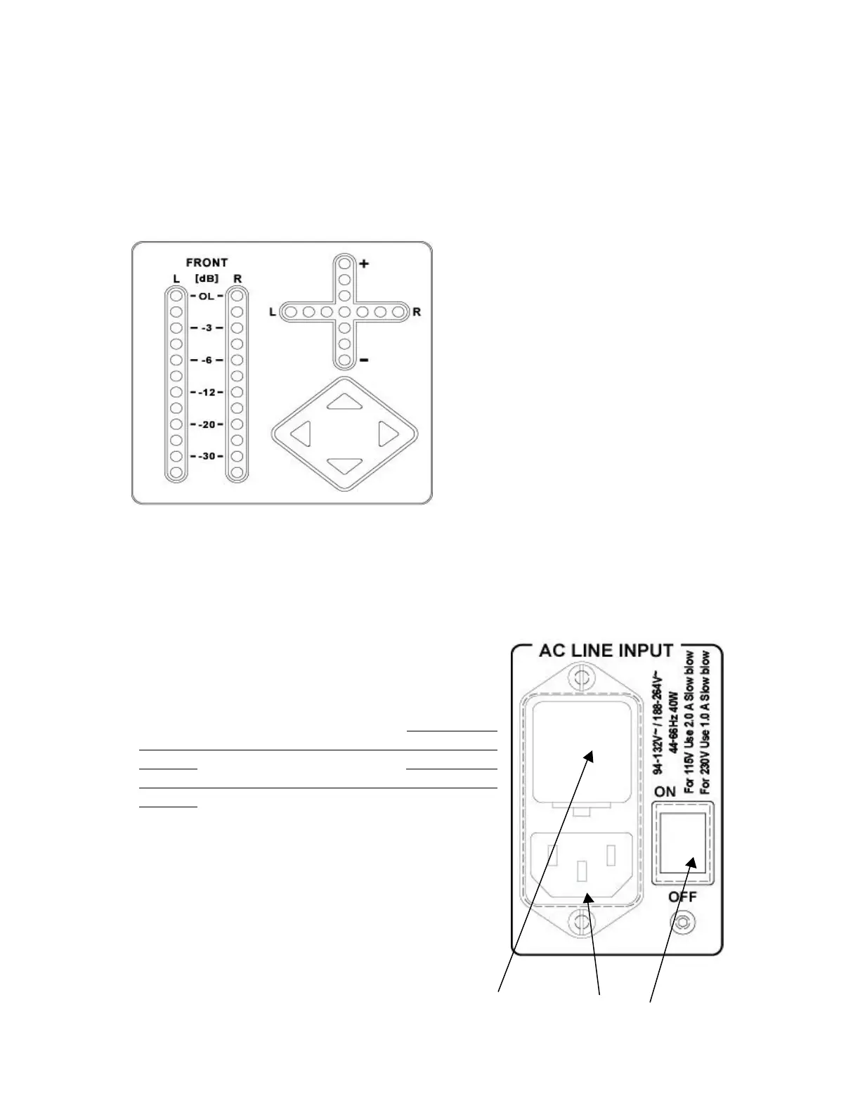
2.0 INPUTS AND OUTPUTS PANEL
2.1 AC INPUT PANEL
“1” is the fuse holder and voltage selector.
The DAC works from 94 V to 132 V (fuses: please
read on the rear panel 2.0 A and not 0.6A on older
versions) and from 188 V to 264 V (fuses: please
read on the rear panel 1.0 A and not 0.3A on older
versions).
Lift the little clip and remove the holder. Select the
corresponding AC voltage and install the fuses. Insert
the holder. Verify that through the holder, the
corresponding AC voltage is shown.
“2” is the AC plug.
“3” is the main power switch.
1 2 3
Once the AC voltage is controlled and the AC cable is connected, switch to ON.