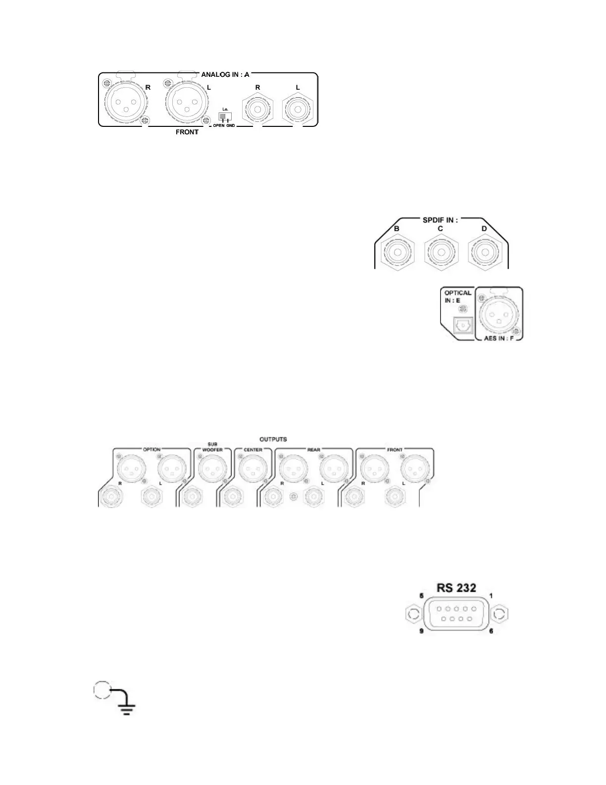
2.2 INPUT PANEL
The “A” input is an analog input source. The connection can be made via the XLR
connectors or via the RCA connectors. Both may not be used simultaniously. The XLR
connectors can be selected as electronically balanced or unbalanced. This depends on the
position of the little switch: If “OPEN” is selected, a balanced signal can be connected, if
“GND” is selected, an unbalanced signal should be delivered to the XLR input. The
analog input source is first converted to a digital source at
a sampling rate of 48 kHz 24 bits.
“B”, “C”, & “D” are the digital SPDIF inputs (75?
terminated). Maximum input clock is 96 kHz.
“E” is the optical input. Before using it remove the black cover by
pulling it. Maximum input clock is 96 kHz.
“F” is the AES input connector. It is a symmetrical digital signal input and support
maximum a clock of 96 kHz.
2.3 OUTPUT PANEL
It is possible to select either the XLR outputs or the RCA (Cinch) outputs. Both may not
be used together. On the NAGRA DAC, only the FRONT outputs are wired.
2.4 RS232 CONNECTOR
This connector is first of all used by the production area inside the
factory and serves also to upgrade the software of the Nagra DAC.
2.5 GROUND CONNECTION
If for any reasons some hum appears, several audio sources can be connected
together via this ground (chassis) connector.