Do you have a question about the Nailor 3000 Series and is the answer not in the manual?
Details calibration charts and part numbers for diamond flow sensors.
Lists available control components for VAV terminal units.
Part numbers and specifications for diamond flow sensors.
Lists control components for dual duct units.
Lists control components for retrofit units.
Setting procedure for electric actuators.
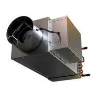
Procedures for inspecting, cleaning, and troubleshooting the fan and motor.
Illustrates the relationship between voltage input and airflow for ECM motors.
Part numbers for SCR and SSR electric heat controllers.
Part numbers for PSC induction motors by size and HP.
Part numbers for ECM motors by size and HP.
Steps to visually inspect the unit for shipping damage.
Safety guidelines for personnel involved in installation.
Procedures for connecting ducts to the unit's inlet and discharge.
Recommendations for ensuring access for maintenance and servicing.
Procedures for inspecting, cleaning, and troubleshooting the fan and motor.
An example of the unit's nameplate label with key information.
Part numbers for diamond flow sensors by inlet size.
Part numbers for EON control cards and related items.
Diagrams showing unit orientations and control side configurations.
Part numbers for SCR and SSR electric heat controllers.
Signal for proving motor blower operation.
Step-by-step guide for mounting EZvav sensors.
Basic maintenance procedures for EZvav sensors.
Connecting the sensor to the controller using an Ethernet cable.
Connecting the controller to a 24-volt power source.
Details on parameters like COMM, BLNC, STPT, FLOW, ADVC, RSTR, etc.
Guidelines for installing CTE-5100 thermostats.
Equations for calculating CFM from VDC and vice versa.
Calibration procedure for the CTE-5101 thermostat.
Procedures for checking actuator movement and airflow readings.
Checking fan operation in occupied mode.
Part numbers for KMC controllers and actuators.
Part numbers for Kreuter thermostats and accessories.