Do you have a question about the Nakamichi 480 and is the answer not in the manual?
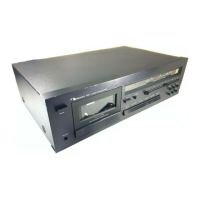
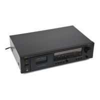
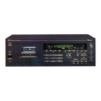
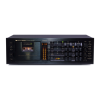
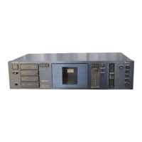
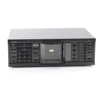
Identifies and describes control functions on the front panel of the Nakamichi 480.
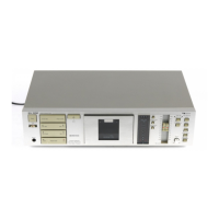
Explains the voltage selector switch for choosing between 120V and 220-240V power.
Details the mechanical workings and components of the cassette deck.
Explains the headblock structure and adjustments for stabilized tape travel.
Describes the sectional view and characteristics of the erase head.
Explains the double capstan system for stable tape tension and wow/flutter.
Details cam operation for controlling mechanism modes like Play, Record, FF/REW.
Covers the audio amplifier circuits used in the device.
Explains the playback equalizer amplifier circuit and its time constants.
Details the record equalizer amplifier circuit and calibration volumes.
Explains the bias oscillator circuit for recording bias and erase signal.
Provides an overview of the mechanism control circuits.
Explains how control buttons function and interlock.
Describes the auto shut-off mechanism for tape end.
Details unattended recording/playback via button lock mechanism.
Explains the circuit generating +12V from +24V for mechanism control.
Describes the power-mute signal for muting amp circuits.
Details the auto shut-off circuit and sensor functions.
Explains the circuit for setting RECORD mode and protection.
Details the conditions for muting the amplifier circuit.
Describes the motor drive circuit for the control motor and cam.
Explains the reel motor governor circuit for speed control.
Instructions to remove the cassette case cover assembly.
Instructions to remove the top cover assembly.
Instructions to remove the bottom cover assembly.
Instructions to remove the front panel assembly.
Instructions to remove the headphone jack assembly.
Instructions to remove the main mechanism assembly.
Instructions to remove the meter assembly.
Instructions to remove lamp PCB assemblies.
Instructions to remove the main PCB assembly.
Instructions to remove the control switch holder.
Instructions to remove the switch PCB assembly.
Instructions to remove volume and control switch PCBs.
Instructions to remove rear panel, transformer, and switch.
Instructions to remove cassette case and cover plate.
Instructions to remove the tape counter assembly.
Instructions to remove capstan motor and flywheel assemblies.
Instructions to remove the sub mechanism chassis assembly.
Instructions to remove control and reel motor assemblies.
Instructions to remove the cam control volume.
Instructions to remove reel hub and idler assemblies.
Instructions to remove cam drive gear and control cam.
Instructions to remove the head mount base assembly.
Instructions to remove pressure rollers and erase head.
Instructions to remove the record/playback head assembly.
Adjusts the control motor driver and cam timing.
Adjusts tape speed using the capstan motor volume.
Adjusts tilt of the record/playback head using a gauge.
Adjusts the stroke of the record/playback head base.
Adjusts tape guides height and erase head stroke.
Adjusts erase head height and tilt using beacons.
Adjusts record/playback head height and azimuth.
Adjusts tape travel using a modified tape.
Adjusts linkage for the record switch.
Adjusts flywheel holder thrust screws for minimal gap.
Adjusts the eject wire and stopper for proper function.
Specifies lubricants for replaced parts.
Provides general instructions for electrical adjustments and measurements.
Adjusts playback frequency response using specific tapes.
Checks the Dolby NR circuit operation and frequency response.
Adjusts bias oscillation frequency and erase current.
Adjusts record amplifier equalizer for frequency response.
Adjusts bias trap for optimal frequency response.
Calibrates record level for different tape types.
Adjusts bias current and overall frequency response.
Measures and adjusts crosstalk between channels.
Measures and adjusts channel separation.
Measures and adjusts tape erasure performance.
Measures and adjusts signal-to-noise ratio.
Measures and adjusts total harmonic distortion.
Measures and adjusts wow and flutter.
Shows mounting diagram and parts for volume PCB.
Shows mounting diagram and parts for control switch PCB.
Shows mounting diagram and parts for switch PCB.
Shows mounting diagram and parts for control PCB.
Shows mounting diagram and parts for auto shut-off PCB.
Shows mounting diagram and parts for lamp PCB L.
Shows mounting diagram and parts for lamp PCB R.
Shows mounting diagram and parts for the main PCB.
Parts list and diagram for the synthesis mechanism.
Parts list and diagram for the front panel assembly.
Parts list and diagram for the synthesis mechanism assembly.
Parts list and diagram for the meter escutcheon assembly.
Parts list and diagram for the control switch holder assembly.
Parts list and diagram for the headphone jack assembly.
Parts list and diagram for the main mechanism assembly.
Parts list and diagram for the chassis assembly.
Parts list and diagram for the flywheel holder assembly.
Parts list and diagram for the sub mechanism chassis assembly.
Parts list and diagram for the main mechanism chassis assembly.
Parts list and diagram for the rear panel assembly.
Parts list and diagram for the reel motor assembly.
Parts list and diagram for the control motor assembly.
Parts list and diagram for the head mount base assembly.
Parts list and diagram for the supply pressure roller assembly.
Parts list and diagram for the take-up pressure roller assembly.
Parts list and diagram for head base assembly C.
Parts list and diagram for cassette case holder L.
Parts list and diagram for cassette case holder R.
Parts list and diagram for auto shut-off assembly.
Parts list and diagram for pneumatic damper assembly.
Parts list and diagram for RP-9E head assembly.
Graph showing playback frequency response curves.
Graph showing record frequency response curves.
Block diagram of the audio amplifier section.
Block diagram of the mechanism control system.
| Type | 2-head, single compact cassette deck |
|---|---|
| Tape Speed | 4.8 cm/s |
| Track System | 4-track, 2-channel stereo |
| Frequency Response | 20Hz to 20kHz (Metal tape) |
| Signal to Noise Ratio | 66dB (Dolby B) |
| Total Harmonic Distortion | 1.0% |
| Weight | 8 kg |
| Tape Type | CrO2, Metal |
| Input | Line |
| Output | Line |
| Heads | 2 (Record/Playback, Erase) |