Do you have a question about the Nakamichi 1000ZXL and is the answer not in the manual?
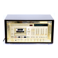
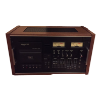
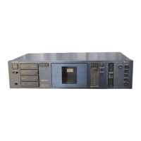
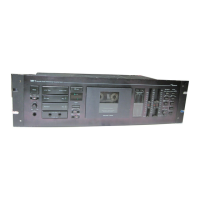
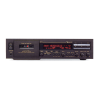
Details on the control functions of the Nakamichi 1000ZXL.
Procedure for removing the cabinet assembly.
Steps to remove cabinet case cover and azimuth alignment cover assemblies.
Procedure for removing the front panel assembly.
Steps for removing the mechanism assembly.
Procedure for removing the logic PCB assembly.
Steps for removing the main PCB assembly.
Procedure for removing the rear panel assembly.
Steps for removing the power supply PCB assembly.
Procedure for removing the FL indicator PCB assembly.
Steps for removing the display holder assembly.
Procedure for removing capstan motor and flywheel assemblies.
Steps for removing the sub mechanism chassis assembly.
Procedure for removing cam control and reel motor assemblies.
Steps for removing reel hub and idler assemblies.
Procedure for removing cam drive and control cam.
Steps for removing the counter pulse generator PCB assembly.
Procedure for removing the head mount base assembly.
Steps for removing pressure roller and erase head.
Procedure for removing playback and record head assemblies.
Procedure for battery replacement.
List of instruments required for measurements.
List of instruments used for maintenance procedures.
Procedure for adjusting the mechanism control cam.
Steps to adjust the offset for the control motor driver.
Procedure for fine-tuning the control motor driver offset.
Procedure for adjusting the reference voltage for various modes.
Details on resistors used for adjustment procedures.
Step-by-step guide for performing adjustments.
Procedure for adjusting the cam timing.
Steps for adjusting the RAMM mode.
Procedure for head base stroke adjustment in RAMM cue mode.
Guide to moving record/playback head indicators.
Procedure for adjusting record speed in play mode.
Procedure for adjusting record speed in RAMM speed mode.
Procedure for playback head speed adjustment in RAMM speed mode.
Procedure for adjusting RAMM gain.
Procedure for adjusting record and playback head tilt.
Procedure for adjusting the head base stroke.
Procedure for adjusting the head tilt.
Procedure for adjusting back tension.
Adjusting playback/record head height and azimuth alignment.
Procedure for adjusting tape travelling.
Procedure for adjusting the flywheel holder.
Procedure for adjusting tape speed.
Lubrication points and procedures.
Procedure for adjusting record speed in play mode.
Steps for adjusting the RAMM mode.
Procedure for head base stroke adjustment in RAMM cue mode.
Guide to moving record/playback head indicators.
Procedure for adjusting record and playback head tilt.
Procedure for adjusting the head base stroke.
Procedure for adjusting the head tilt.
Procedure for adjusting back tension.
Adjusting playback/record head height and azimuth alignment.
Procedure for adjusting tape travelling.
Procedure for adjusting the flywheel holder.
Procedure for adjusting tape speed.
Lubrication points and procedures.
Procedure for adjusting tape guides and erase head stroke.
Procedure for adjusting erase head height and tilt.
Adjusting playback and record head height and azimuth alignment.
Procedure for adjusting record head stroke.
Overview of electrical adjustments and measurements.
Detailed instructions for performing adjustments and measurements.
Procedure for adjusting frequency response.
Procedure for checking the Dolby NR circuit.
Procedure for recording bias trap adjustment.
Procedure for adjusting playback level.
Measurement of playback frequency response.
Adjustment of maximum bias current.
Procedure for bias current adjustment.
Procedure for oscillator level adjustment.
Procedure for adjusting the A/D converter offset.
Measurement of A/D converter frequency response.
Procedure for record head height and azimuth alignment.
Procedure for playback head height and azimuth alignment.
Procedure for overall frequency response adjustment.
Procedure for crosstalk measurement.
Procedure for channel separation measurement.
Procedure for erase measurement.
Procedure for speed ratio measurement.
Procedure for total harmonic distortion measurement.
Procedure for subsonic filter measurement.
Procedure for wow and flutter measurement.
Adjustment for peak-to-peak level.
Measurement of record current frequency response.
Adjusting high-frequency response.
Adjusting low-frequency response.
Mounting diagram and parts list for fuse PCB assembly.
Mounting diagram and parts list for power supply PCB assembly.
Mounting diagram and parts list for pin jack PCB assembly.
Mounting diagram and parts list for MIC jack PCB assembly.
Mounting diagram and parts list for RAMM control switch PCB assembly.
Mounting diagram and parts list for function switch PCB assembly.
Mounting diagram and parts list for mechanism control switch PCB assembly.
Mounting diagram and parts list for speed calibration PCB assembly.
Mounting diagram and parts list for counter pulse generator PCB assembly.
Mounting diagram and parts list for shut-off PCB assembly.
Mounting diagram and parts list for FL indicator PCB assembly.
Mounting diagram and parts list for detector PCB assembly.
Mounting diagram and parts list for record Dolby NR PCB assembly.
Mounting diagram and parts list for record equalization amplifier PCB assembly.
Mounting diagram and parts list for MIC amplifier and volume PCB assembly.
Mounting diagram and parts list for playback amplifier and Dolby NR PCB assembly.
Mounting diagram and parts list for main PCB assembly.
Mounting diagram and parts list for logic PCB assembly.
Mounting diagram and parts list for CPU PCB assembly.
Mounting diagram and parts list for CPU PCB B assembly.
Mounting diagram and parts list for RAMM PCB assembly.
Mounting diagram and parts list for Display PCB assembly.
Parts list and diagram for synthesis assembly.
Parts list and diagram for synthesis mechanism assembly A01.
Parts list and diagram for cabinet assembly A02.
Parts list and diagram for front panel assembly B01.
Parts list and diagram for FL indicator assembly B02.
Parts list and diagram for synthesis mechanism sub assembly B03.
Parts list and diagram for rear panel assembly B04.
Parts list and diagram for headphone jack assembly C01.
Parts list and diagram for display house assembly C02.
Parts list and diagram for front escutcheon assembly C03.
Parts list and diagram for front escutcheon assembly C04.
Parts list and diagram for mechanism assembly 1000ZXL D01.
Parts list and diagram for chassis sub assembly D02.
Parts list and diagram for flywheel holder assembly E01.
Parts list and diagram for sub mechanism chassis assembly E02.
Parts list and diagram for main mechanism chassis assembly E03.
Parts list and diagram for reel motor assembly F01.
Parts list and diagram for control motor assembly F02.
Parts list and diagram for azimuth alignment motor assembly F03.
Parts list and diagram for head mount base assembly G02.
Parts list and diagram for supply pressure roller assembly G03.
Parts list and diagram for take-up pressure roller assembly G03.
Parts list and diagram for head base assembly E G04.
Parts list and diagram for cassette case holder L assembly G08.
Parts list and diagram for cassette case holder R assembly G09.
Parts list and diagram for auto shut-off assembly G07.
Parts list and diagram for pneumatic damper assembly G08.
Parts list and diagram for azimuth motor assembly H01.
Parts list and diagram for P-BL playback head assembly I01.
Parts list and diagram for R-BL record head assembly I02.
Overall timing chart for Nakamichi 1000ZXL operations.
Details on auto calibration and RAMM control procedures.
Flow chart illustrating the auto calibration process.
Timing chart for RAMM coding operations.
Graph and details of playback frequency response.
Graph and details of record current frequency response.
Block diagram for amplifier and A.B.E.L. CPU control.
Block diagram for mechanism control and RAMM control.
Schematic diagram of the amplifier section.
Schematic diagram of the CPU section.
Schematic diagram of the mechanism control section.
Block diagrams for integrated circuits.
Schematic diagram of the remote controller.
Mounting diagram and parts list for the remote controller.
Mounting diagram and parts list for control switch PCB.
Mounting diagram and parts list for display PCB.
Mechanism assembly and parts list for the remote controller.
| Tape Speed | 4.76 cm/s |
|---|---|
| Frequency Response | 20Hz to 22kHz (Metal tape) |
| Signal to Noise Ratio | 72dB (Dolby C) |
| Track System | 4-track, 2-channel stereo |
| Heads | 3 (erase, record, playback) |
| Total Harmonic Distortion | 0.8% |
| Motor | 3 |
| Tape Type | Type I, Metal |
| Inputs | Line, Microphone |
| Outputs | Line |
| Type | 3-head, single compact cassette deck |