Do you have a question about the Nakamichi MR-1 and is the answer not in the manual?
Provides an overview of the service manual's scope and applicability to different regions.
Lists packing materials and owner's manual part numbers for the device.
Details the procedure for adjusting head tilt using a tilt check gauge.
Explains how to check the head base stroke using a stroke check gauge.
Covers adjustment for erase head stroke and checking tape guide height.
Outlines the process for adjusting erase head height and tilt.
Details procedures for adjusting playback and record head height and azimuth alignment.
Describes how to measure and adjust the torque of the take-up pressure roller.
Explains how to check tape travel for proper contact and smoothness.
Details the adjustment of the eject damper speed.
Explains how to adjust reel motor speed in play mode using a torque meter.
Outlines the procedure for adjusting tape speed using a frequency counter.
Specifies lubricants for specific parts when replaced.
Provides general instructions and notes before performing electrical adjustments.
Explains playback frequency response adjustment using specific tapes and circuits.
Shows the synthesis mechanism assembly diagram.
Displays the front panel assembly diagram and parts.
Provides a diagram and parts list for the synthesis mechanism assembly.
Shows the front chassis assembly diagram and parts.
Diagram and parts list for the cover plate assembly.
Diagram and parts list for the rear panel assembly.
Mounting diagrams for Power, Shut-off, Tape LED, MPX Filter, Headphone Volume, and Volume PCBs.
Mounting diagrams for Input/Output and Amplifier PCBs like Input Bal. Amp, Unbal. Input, Output Bal. Amp.
Mounting diagrams for Ext. NR, Meter Amp, Dolby NR Switch, and Control Switch PCBs.
Mounting diagrams for Counter, Tape Switch, and Fuse PCBs.
Mounting diagram for the main PCB.
Displays the overall schematic diagram of the Nakamichi MR-1.
Shows block diagrams for integrated circuits used in the device.
Illustrates the timing relationships between various operational modes.
Shows frequency response curves for equalizer amplifier circuits.
Block diagram of the amplifier section, showing signal flow.
Block diagram of the mechanism control section, detailing its operation.
| Track System | 4-track, 2-channel stereo |
|---|---|
| Frequency Response | 20Hz to 20kHz (Metal tape) |
| Wow and Flutter | 0.04% (WRMS) |
| Total Harmonic Distortion | 0.8% |
| Output | 0.5V (line) |
| Weight | 6.5 kg |
| Tape Speed | 4.76 cm/s |
| Heads | 1 x erase |
| Tape Type | Type I, Type II, Type IV |
| Noise Reduction | B, C |
| Input | 50mV (line) |
| Inputs | Line |
| Outputs | Line |
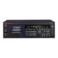
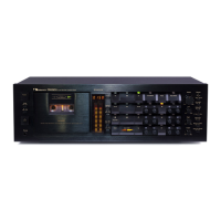
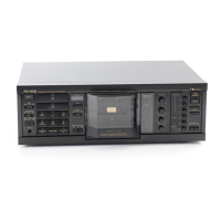
| Type | 3-head, single compact cassette deck |