Do you have a question about the Nakamichi CR-3 and is the answer not in the manual?
Selects operating voltage (110/127/220/240V) on the rear panel.
Adjusting the tilt of record and playback heads.
Verifying the stroke travel of the head base.
Adjusting erase head stroke and tape guide height.
Adjusting erase head height and tilt for optimal performance.
Adjusting playback and record head height and azimuth alignment.
Adjusting tape speed using frequency counter and volume control.
Aligning the playback head for optimal track contact.
Adjusting playback head azimuth for maximum output.
Adjusting playback frequency response characteristics.
Adjusting bias oscillation frequency and erase current.
Adjusting the height of the record head.
Aligning the record head azimuth.
Calibrating record level and bias current.
Adjusting the overall record/playback frequency response.
Detailed schematic diagrams for various PCB assemblies.
Frequency response graphs for playback and record equalization.
| Motor | DC Servo Motor |
|---|---|
| Track System | 4-Track, 2-Channel Stereo |
| Total Harmonic Distortion | 0.8% |
| Input | Line In |
| Output | Line Out |
| Heads | 3 |
| Tape Type | Metal |
| Frequency Response | 20 Hz - 20 kHz |
| Noise Reduction | Dolby B, Dolby C |
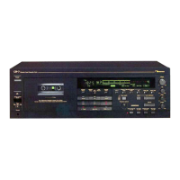
| Type | Stereo Cassette Deck |