Do you have a question about the Nakamichi BX-2 and is the answer not in the manual?
Check and adjust tape guide height for record/playback and erase heads.
Check the head base stroke for proper clearance.
Align record/playback head azimuth and check its height.
Adjust the torque of the pressure roller.
Verify proper tape path and movement.
Adjust the speed of the eject damper movement.
Adjust reel motor speed during playback.
Adjust the tape playback speed.
Apply specified lubricants when replacing certain parts.
Step-by-step instructions for performing adjustments and measurements.
Calibrate record level and adjust recording bias current.
Adjust frequency response for various tape types.
Measure the crosstalk between audio channels.
Measure the channel separation.
Measure the tape erasure performance.
Measure the signal-to-noise ratio.
Measure the total harmonic distortion.
Measure wow and flutter.
Check the operation of the Dolby NR B-Type circuit.
Check the operation of the Dolby NR C-Type circuit.
Exploded view and parts list for the synthesis mechanism.
Parts list and diagram for Synthesis Mechanism Ass'y (A01).
Parts list and diagram for Mechanism Ass'y (B01).
Mounting diagram and parts for the power switch PCB assembly.
Mounting diagram and parts for the pin jack PCB assembly.
Mounting diagram and parts for the volume PCB assembly.
Mounting diagram and parts for the Dolby NR switch PCB assembly.
Mounting diagram and parts for the indicator PCB assembly.
Mounting diagram and parts for the timer switch PCB assembly.
Mounting diagram and parts for the control switch PCB assembly.
Mounting diagram and parts for the shut-off PCB assembly.
Mounting diagram and parts for the counter PCB assembly.
Important notes and precautions for service technicians.
Block diagrams illustrating integrated circuit functions.
Block diagram detailing the amplifier section's signal flow.
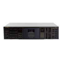
| Type | Cassette Deck |
|---|---|
| Track System | 4-track, 2-channel stereo |
| Tape Speed | 4.76 cm/s |
| Noise Reduction | Dolby B |
| Total Harmonic Distortion | 1.0% |
| Motor | DC servo motor |
| Tape Type | CrO2, Metal |
| Frequency Response | 20 Hz to 20 kHz |
| Input | 50mV (line) |
| Output | 0.5V (line) |
| Inputs | Line |
| Outputs | Line |