Do you have a question about the NAMCO Final Furlong 2 and is the answer not in the manual?
This document provides comprehensive conversion instructions for the "Final Furlong 2" arcade game, detailing the process of upgrading an existing game unit. The manual emphasizes the importance of thorough testing and problem rectification before commencing any conversion work, advising users to record all current game settings to ensure proper configuration of the new Game PCB. A critical safety warning highlights the necessity of switching off and disconnecting the game from the mains supply before any work begins, along with a caution to ensure adequate space for safe header removal. Users are also reminded to carefully manage screws and washers during disassembly, as these components will be required for reassembly.
The conversion process begins with preliminary steps focused on removing the ride assembly. This involves raising twelve adjustable feet—four on the monitor cabinet and four on each ride base assembly—after slackening their lock nuts with a spanner. Following this, eight security screws (M5x12) are removed to detach both Base Front Cover Plates. The ride base is then disconnected from the monitor cabinet by removing four hex head screws (M10x35) along with their flat and spring washers. The ride assembly is then carefully pulled away from the monitor cabinet, just enough to access and disconnect the wiring harness, taking care not to stretch the wires. Once disconnected, the ride assembly can be moved completely away from the monitor cabinet.
Next, the header assembly is addressed. The manual issues a significant warning regarding the header assembly's high center of gravity and advises that at least two people should be involved in its removal and reinstallation to prevent accidents. The process starts by removing two pozi head screws (M4x12) with flat and spring washers, which secure the connector cover plate. After removing the plate, the connector is disconnected. Two additional pozi head screws (M5x16) with flat and spring washers are then removed. The header assembly is subsequently slid forward to disengage it from its retaining bracket before being completely removed.
The ride assembly conversion involves replacing decals. Users are instructed to remove the existing Horse Rear Decals from both sides of the horse, then fit the new Horse Rear Decals in their place. Additionally, new decals are to be applied to the rear of the Ride Base.
For the header assembly, the conversion involves removing ten security screws (M5x16) and the existing header acrylic, which is no longer required. Two pozi head screws (M4x12) are then removed to detach the Top Bracket, also no longer needed. New top brackets are then fitted using four supplied Torx security screws (M5x12 black). Following this, the new Header Acrylic is installed using ten supplied Torx security screws (M5x16 chrome). After these steps, the header assembly is refitted, its connector reconnected, and the connector cover plate refitted.
The monitor cabinet conversion focuses on replacing decals. All old decals are to be removed, with the exception of the Monitor Middle Lower Decal. New decals are then applied to the monitor cabinet as illustrated in the manual.
Fitting the new Front Vac-Form is another step in the conversion. This involves attaching the new Vac-Form Bracket using two supplied Torx security screws (M5x16 black). Subsequently, the new Vac-Form itself is fitted using four supplied Torx security screws (M5x16 black).
A crucial part of the conversion is replacing the Game PCB. All connectors on the existing Game PCB, including the fan connectors, must be disconnected. The manual notes that some cables will be replaced with new ones. Two pozi head screws (M6x25) are removed from the right-hand end of the Game PCB, while two similar screws on the left-hand end are slackened to allow for the removal of the old Game PCB. The old and new Game PCBs are then placed next to each other. Eight pozi head screws (M4x50) are removed to detach the fans from the old Game PCB (four screws per fan). A critical warning is issued here: the fans must be fitted to the new Game PCB in exactly the same way up using four pozi head screws (M4x50) (two screws per fan), as failure to do so will result in irreparable damage to the new Game PCB.
After the fans are installed, the new Game PCB is refitted, and the four pozi head screws (M6x25) are fully tightened. New cables linking the I/O boards to the Front Cover Boards, and a new HSB cable linking the two front cover boards, are then connected. A two-way connector with yellow and black wires, located to the right of the Switchmode Power Supply, is identified and separated. A new break-out cable is then fitted to these two-way connectors, with its other ends connected to the front cover boards as shown in the diagram. Finally, the existing connectors are refitted to the I/O Boards and Front Cover Boards. A specific note advises ensuring that when refitting the D Sub connectors to the Front Boards, connector 2 is fitted to the board nearest the rear of the cabinet, and all connector retaining screws are fully tightened.
The replacement of the Repeater (Link) PCB is also detailed. One pozi head screw (M5x12) is removed to detach the Link Cover Bracket. Two pozi head screws (M4x12) are then removed to take out the Link PCB complete with its mounting bracket. The connectors are disconnected. The new Link PCB, complete with its mounting bracket, is then refitted using two pozi head screws (M4x12). Finally, a new Communication cable is fitted.
The re-assembly and test phase marks the completion of the conversion. Users are instructed to reassemble the Ride Assemblies to the Monitor Cabinet, taking care not to trap any wires. The Mains-In is reconnected, and the unit is switched ON. Both players must then be reinitialized, referring to section 6-8, page 58 of the Operators Manual. All game settings are then reset to the required levels, as detailed in section 6-7 'Test Mode', page 47 of the Operators Manual. The document concludes by stating that the conversion is now complete.
The manual also includes a comprehensive list of new part numbers required for the conversion, categorized by item and description, along with corresponding part numbers. These include various decals for the cabinet sides, instruction panels, cabinet fronts, and monitor vac-forms, as well as number decals. Additional parts listed cover the horse rear decals, base decals, truss cover, signboard cover, centre logo decal, and light plate. This detailed parts list ensures that all necessary components are identified for a successful conversion.
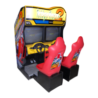
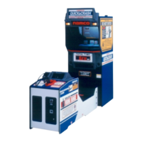
| Game Title | Final Furlong 2 |
|---|---|
| Manufacturer | NAMCO |
| Release Year | 1998 |
| Genre | Sports (Horse Racing) |
| Players | 2 |
| Monitor | CRT |
| Developer | NAMCO |