EasyManua.ls Logo

NANOTEC SMCI33 - User Manual

NANOTEC SMCI33
28 pages
Print Icon
To Next Page IconTo Next Page
Loading...
Technical Manual
Stepper driver
SMCI33
NANOTEC ELECTRONIC GmbH & Co. KG
Gewerbestraße 11
D-85652 Landsham near Munich, Germany
Tel. +49 (0)89-900 686-0
Fax +49 (0)89-900 686-50
info@nanotec.com

Questions and Answers

  • T
    Terri WarrenAug 15, 2025
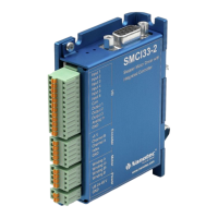
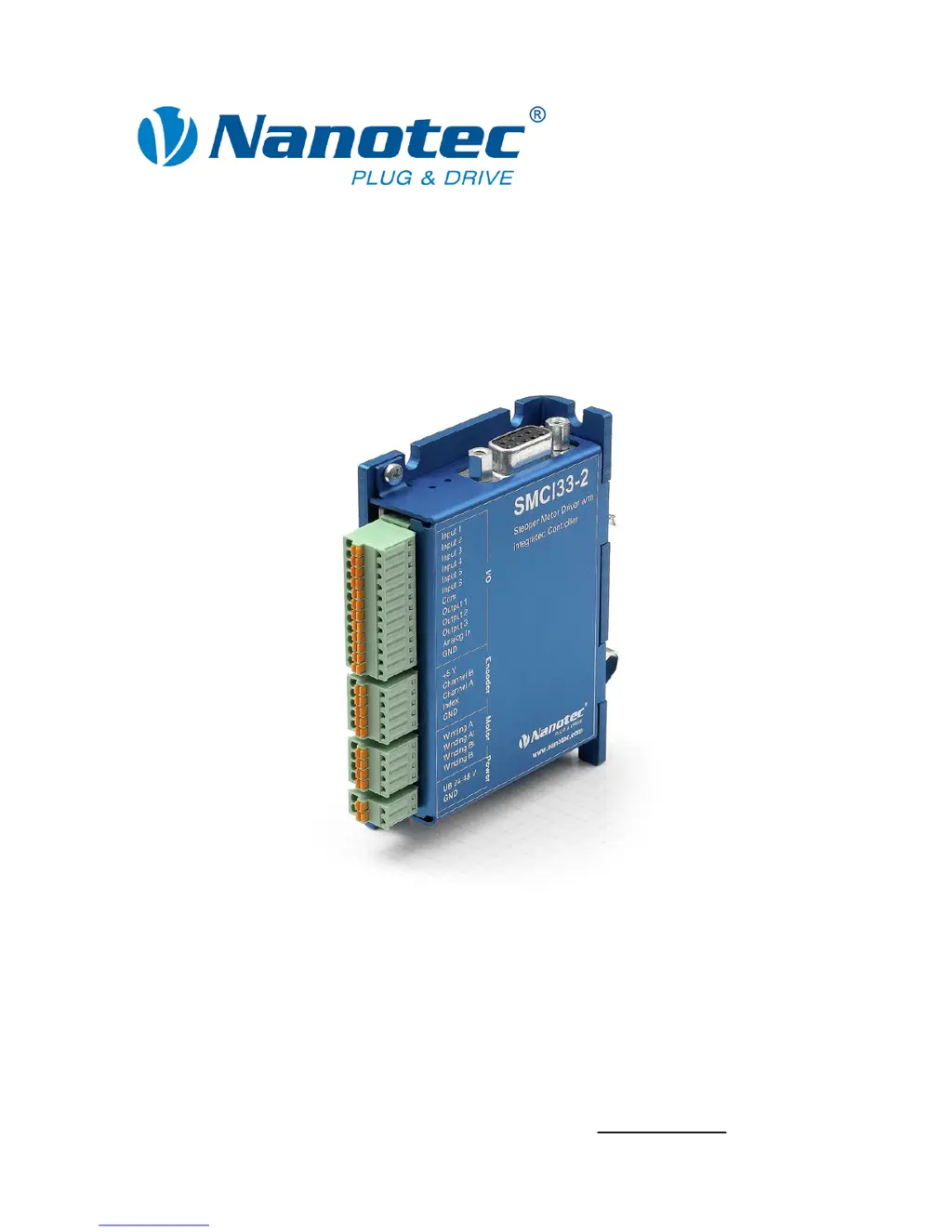
    What to do if the red LED on NANOTEC Controller SMCI33 is lit?
    • M
      Michael JohnsonAug 16, 2025
      If the red LED on your NANOTEC Controller SMCI33 is lit, it could indicate either an overtemperature of the power electronics (above 75 °C) or an undervoltage condition. If it's due to overtemperature, switch off the driver and allow it to cool. Disconnecting the SMCI33 from the power supply unit will reset the error. In case of undervoltage, check the voltage supply to ensure it meets the required specifications.
  • E
    Erika BriggsOct 31, 2025
    How to fix NANOTEC SMCI33 when driver is not ready?
    • E
      Erin LopezOct 31, 2025
      If the NANOTEC Controller driver isn't ready, it could be due to several reasons. First, check that you've selected the correct COM port in the 'Communication' tab, matching the port your SMCI33 is connected to, which you can verify in your PC's device manager. Ensure the communication cable is properly connected, using the recommended NANOTEC RS232-RS485 converter (Order number: ZK-RS485-RS232). Also, verify that you've set the correct module address, consulting the NANOPRO manual if needed. Confirm that the SMCI33's power supply is active and at the correct voltage. Close any other programs that might be blocking the COM port. Finally, if inadmissible data was sent during a travel profile, click the button to stop it, allowing the SMCI33 to return to the 'Ready' state before resending d...

Summary

2 Connection and Commissioning

Closed-Loop Current Control

Explains the closed-loop control mechanism using encoder feedback for precise motor control.

2.1 Connection Diagram

Provides the wiring diagram for connecting the stepper driver, motor, and other components.

3 Connections and Circuits

3.1 Inputs and Outputs (I;O): Connector X1

Details the assignment, functions, and circuits of Connector X1 for digital and analog I/O.

3.2 Encoder Connection: Connector X2

Details how to connect an optional encoder to Connector X2 for position feedback.

3.3 Stepper Motor Connection: Connector X3

Provides instructions for connecting the stepper motor windings to Connector X3.

3.4 Voltage Supply Connection: Connector X4

Details the connection requirements and diagrams for the voltage supply to Connector X4.

3.5 Interface RS485 Network: Connector X5

Explains the RS485 interface connection for networking up to 32 drivers.

RS485 Network Circuit Diagram

Illustrates the circuit diagram for setting up an RS485 network with multiple units.

RS485 Connection Requirements

Outlines essential requirements for establishing reliable RS485 network connections.

4 Operating Modes

5 Reference Runs and Limit Switch Behavior

6 Troubleshooting

Possible Errors and Rectifications

Lists common errors, their causes, and rectification steps for driver issues.

7 Technical Data

NANOTEC SMCI33 Specifications

General IconGeneral
BrandNANOTEC
ModelSMCI33
CategoryController
LanguageEnglish

Related product manuals