Do you have a question about the Napa 85-640 and is the answer not in the manual?
| Brand | Napa |
|---|---|
| Model | 85-640 |
| Category | Battery Charger |
| Language | English |
Warns about explosive gases from lead-acid batteries and stresses following instructions.
Follow safety instructions from manufacturers and on equipment containing batteries.
Charge only rechargeable lead-acid batteries to prevent injury or damage.
Use only manufacturer-recommended attachments to avoid fire, shock, or injury.
Always have someone nearby when working around lead-acid batteries.
Keep fresh water and soap nearby for acid contact emergencies.
Wear eye protection, clothing protection, and rubber-soled shoes.
Wash skin/clothing immediately with soap and water; flush eyes with water for 10 mins.
If removing battery, disconnect grounded terminal first. Turn off vehicle accessories.
Ensure the area around the battery is well ventilated during charging to disperse gases.
Clean battery terminals carefully, keeping corrosion away from eyes.
Add distilled water to the specified level; do not overfill. Follow capless battery instructions.
Charger must be grounded. Plug into a properly installed and grounded outlet.
Temporary adapters may be used; ensure outlet plate screw is grounded.
Locate charger as far as charger cables permit from the battery.
Never place charger directly above battery; gases will corrode charger.
Never allow electrolyte to drip on charger when taking gravity readings or filling.
Operate charger only in well-ventilated area, free of dangerous vapors.
Set switches to OFF (O) and disconnect AC cord before connecting/disconnecting clamps.
Attach clamps securely to battery posts, twist to ensure good connection and prevent sparking.
Apply emergency brake, shift to neutral/park. Turn off vehicle loads.
Check battery post polarity; POSITIVE post usually has a larger diameter than NEGATIVE.
Connect POSITIVE clamp to battery, NEGATIVE clamp to chassis away from battery.
Connect NEGATIVE clamp to battery, POSITIVE clamp to chassis away from battery.
If removing battery, always remove the grounded terminal first.
Connect the POSITIVE (RED) charger clamp to the POSITIVE (POS., P, +) post of the battery.
Position self away from battery. Connect NEGATIVE (BLACK) clamp to free end of cable.
Disconnect in reverse sequence of connection, breaking first connection farthest from battery.
Check refillable battery charge using a hydrometer and specific gravity readings.
Test sealed-top batteries using a high-resolution voltage tester.
Temperature significantly affects battery efficiency and power requirements.
Charger adjusts time for complete, efficient, and safe charging; guidelines provided.
Provides estimated charging times based on battery size and charging rate.
Battery state affects charge time; use built-in tester for estimation.
Higher rated batteries take longer to charge. Rating affects charge speed.
Batteries of the same voltage can be connected in parallel for maintenance charging.
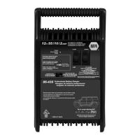
Sets the digital display function to Battery %, Voltage, or Alternator %.
Selects the battery type for charging: 12V Standard, AGM, Gel Cell, or 6V Standard.
Sets the maximum charge rate: 2A, 15A<>40A, 125A Engine Start, or OFF.
Install cord wrap cleats by aligning tabs and pushing until they snap.
Connect charger, press button until ENGINE START LED is lit.
Crank engine for no more than 5 seconds. Wait 3 minutes before re-cranking.
Charger waits to deliver 125A until engine is being cranked.
Charger enters a mandatory 3-minute cool down state after cranking.
Charger has a built-in tester displaying battery voltage or relative charge estimate.
Steps to use charger as battery tester: connect clamps, connect power, select type, read display.
Charger operates as tester initially; selecting charge rate activates charger mode.
Pressing display or type buttons within 15 mins keeps unit in tester mode indefinitely.
Connect clamps, connect power, start vehicle, turn on headlights, read display.
Alternator percent display range 0-199. Cannot set to ALTERNATOR % during charging.
Clean clamps each time charger is used to prevent corrosion from battery fluid.
Coil cords when charger is not in use to prevent damage.
Other servicing should be performed by qualified service personnel.
Ensure charger is not in tester mode; press CHARGING/STARTING button to activate charging.
Check for accidental diagnostic mode activation; unplug and replug charger.
Check battery type selection or if battery did not reach full charge within 24 hours.
Battery may be fully charged; turn on headlights to reduce voltage if needed.
Two-year limited warranty for defects in material or workmanship; proof of purchase required.
Contact customer service for assistance or warranty returns.