StarLink
™
SLE Commercial LTEVI & LTEAI Series Dual-Path Alarm Communicators -- Installation Instructions 7
the radio directly to the 12V of the control panel. Program
the radio to report all troubles on OUT1, Common and
N/C.
You can also wire across the dedicated zone on a GEMC-
EZM8. Thus when a radio trouble is detected, the radio
OUT1 activates the control panel zone, and the panel
generates a local annunciation.
Optionally, you may also wire the FACP Trouble Relay to
IN2; Common and N/O terminals in parallel with a 10k
EOLR. With Gemini C-Series (GEMC) control panels, we
recommend using the Fire Aux Relay. Program the Fire
Aux Relay to activate as a trouble relay. Wire this relay to
the StarLink module IN2 terminal; by wiring the EOLR in
parallel with the Common and N/O of the OUT1 relay.
Note: We recommend using the text "Radio Trouble"
as the Zone Description.
StarLink Radio Supervision
If the two Telco wires (DACT interconnect wiring to the
radio) between the StarLink radio and the control panel
are cut or otherwise disconnected, the control panel must
detect and generate a local trouble indication. Program
the control panel for telephone supervision. Program the
StarLink radio using the Management Center Advanced
Features screen (at www.NapcoNOC.com) to enable
Tip/Ring Wiring Fault Report. Refer to wiring diagram.
Supervision Time Schedule Considerations
If a status change (alarm trouble, etc.) is transmitted, the
radio supervision timer is restarted.
For example, if a status change is sent, the next regular
supervision transmission will occur at the interval deter-
mined by your rate plan.
Configuration Download / Firmware Updates
Technician on site required.
For Commercial Installations a technician is required to be
on site during any reprogramming of the radio or control
panel and must perform / re-perform acceptance testing.
To perform a download or update the radio firmware,
jumper 1 must be removed. UL requires that the jumper
be replaced after the download is complete. Failure to
replace the jumper would allow downloads to the ra-
dio without a technician on-site.
For Residential installations jumper 1 may be removed to
permit uploading and downloading without a technician on
site, however, the dealer is responsible for ensuring the
system is operating correctly after any downloads or
changes to the system.
Cover Tamper
The SLE series radios in the metal housings may option-
ally have front and rear tamper switches installed (GEM-
Tamperkit) and wired to the control panel (see page 14).
Note: The tamper switch on the radio PC board is not
used in this housing (but continues to function if pressed).
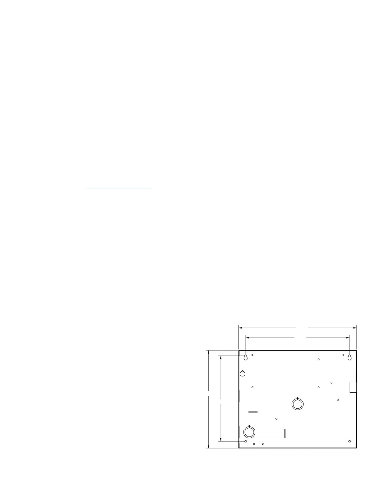
10-1/8"
11-1/2"
9-1/2"
9-21/64"
Red and White Metal Housing Dimensions (inches)
 Loading...


