StarLink
™
SLE-LTEVI-FIRE Commercial Series Dual-Path Alarm Communicator -- Installation Instructions 1
ADDITIONAL COMPONENTS
In addition to the SLE-LTEVI-FIRE listed above, the fol-
lowing sub-assemblies are available:
SLE-WIFI-MODULE - Allows your Napco StarLink
™
device
to connect to the Internet by means of a wireless (Wi-Fi)
link, eliminating a wired Ethernet cable connection.
Note: 7AH battery required when using the SLE-
WIFI-MODULE. For more information, see WI2191.
SLE-DLCBL - Download Cable, 6 feet.
SLE-ANTEXT30 - Extended antenna with 30 feet of cable
SLE-ANTEXT50 - Extended antenna with 50 feet of cable
SLE-ANTEXT75 - Extended antenna with 75 feet of cable
(Any suitable external cellular antenna is permitted by
UL). Always follow the manufacturer's installation in-
structions. Note: Antennas are not Listed by UL. For
LTE radios where an External Antenna needs to be in-
stalled outside of the room in which the radio is installed
(maximum 30 meters (98 feet) in Residential applica-
tions), please use RF Transmitter Board
9SLELTEEXAPSLD available from our Customer Ser-
vice Department, if not provided. The
9SLELTEEXAPSLD is identified by "two red dots" locat-
ed on the lower right corner of the board. See WI2239
included with the 9SLELTEEXAPSLD for the simple in-
stallation procedure.
SPECIFICATIONS
Electrical Ratings for +12V / 24V (powered by the con-
trol panel)*
Input Voltage: 10-25VDC regulated (power-limited out-
put from Listed control panel).
Input Current:
10VDC standby: 162mA
12VDC standby: 125mA
15VDC standby: 110mA
24VDC standby: 100mA
25VDC standby: 100mA
Wi-Fi Module: (Optional) Add 40mA to the above.
(With peak RF transmission current of 300mA).
Electrical Ratings for the IN 1 Fire Input:
Input Voltage: 9-25VDC.
Maximum Input Current: Up to 2mA from FACP NAC
circuit
WI2326LF 12/18
333 Bayview Avenue, Amityville, New York 11701
For Sales and Repairs, (800) 645-9445
For Technical Service, (800) 645-9440 or visit us at
http://tech.napcosecurity.com/
(Note: Technical Service is for security professionals only)
Publicly traded on NASDAQ Symbol: NSSC
© NAPCO 2018
INTRODUCTION
The SLE-LTEVI-FIRE Dual-Path Alarm Communicator is
specifically designed to interface with FACP (Fire Alarm
Control Panels) and to comply with UL 864. The SLE-
LTEVI-FIRE is equipped with two dry relays, one for a
trouble output and one for an auxiliary output. The unit is
also equipped with four supervised inputs to report a Fire
Alarm, a Fire Trouble, a Water Flow Alarm and a Supervi-
sory Alarm, each triggered from the N/O and Common ter-
minals of the associated FACP output relays.
When connected to a FACP with one or two standard RJ-
45 telephone inputs, the SLE-LTEVI-FIRE provides two
RJ-45 outputs to satisfy both telephone inputs. The prima-
ry RJ-45 output is supervised and reports a trouble to the
central station upon any open or short on the primary RJ-
45 wires that prevent reporting. The secondary telephone
line is supervised by the FACP; when a line fault is detect-
ed, a trouble is reported to the central station through the
primary telephone line.
When connected to a FACP without digital dialing capabil-
ity, the StarLink
™
SLE-LTEVI-FIRE Dual-Path Commercial
Fire alarm capture radio communicator is a fully super-
vised, wireless digital two-way subscriber unit supported by
an extensive nationwide wireless network. The SLE-
LTEVI-FIRE is compatible with most 12 or 24VDC alarm
control panels (always adhere to the documentation provid-
ed by the control panel manufacturer). Mount the unit to a
single-, dual-, or three-gang electrical box and route the
wires through the back knockout(s), or as specified by local
codes. See WI2140 for programming information.
The SLE-LTEVI-FIRE communicator uses proprietary
data-capture technology that captures the alarm report
from the control panel and transmits the alarm signals to
the SLE Control Center; the alarm signals are then for-
warded to ANY central station via Contact ID or 4/2 via
DACT from the NOC or Sur-Gard System II, Sur-Gard Sys-
tem V, Bosch D6100IPV6 or Bosch D6600 Receiver (with
ITS-D6686 Ethernet Adapter) via TCP/IP using standard
line security. The SLE Control Center reports a trouble
signal in the event that the network does not receive the
expected supervision signal from the wireless communica-
tor. In addition, the SLE-LTEVI-FIRE is powered directly
from the control panel.
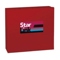
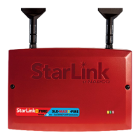
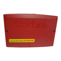
SLE-LTEVI-FIRE - Commercial / Residential Fire LTE Veri-
zon Network Compatible GSM alarm capture Communi-
cator. SIM card included. Red plastic enclosure. Rated
nominal 12/24VDC input.
StarLink™
Commercial SLE-LTEVI-FIRE
Dual-Path Alarm Communicator
INSTALLATION INSTRUCTIONS
*For Commercial Fire installations, a UL Listed Fire Alarm regulated power
supply or FACP regulated auxiliary output is required.
AGENCY LISTINGS
UL 864 Standard For Control Units and Accessories For
Fire Alarm Systems, 10th Edition






 Loading...