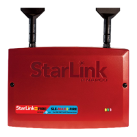
StarLink SLE-MAX2-FIRE Commercial Series Sole/Dual-Path Alarm Communicator -- Installation Instructions 1
and transmits the alarm signals to the SLE Control Center.
The alarm signals are then forwarded to ANY central station
via Contact ID, (SIA is translated to CID by the communicator
see WI2140 on the NOC) or 4/2 via DACT from the NOC or to
the Napco Virtual IP Central Station Receiver (NCSR), or Sur-
Gard System II, Sur-Gard System V, Bosch D6100IPV6 or
Bosch D6600 Receiver (with ITS-D6686 Ethernet Adapter) via
TCP/IP using standard line security (for Commercial Burglary
installations only IP Receivers may be used). The SLE Con-
trol Center reports a trouble signal in the event that the net-
work does not receive the expected supervision signal from
the wireless communicator. In addition, the SLE-MAX2-FIRE
is powered directly from the control panel.
SIA Dial Capture (Converted to CID)
When the fire alarm control panel (FACP)
is reporting with the SIA format, insert the
SLE-MF-JMP jumper into J8 with the
white line towards the left side of the com-
municator as shown below, then program
the communicator in the NOC
(www.NapcoNOC.com) as follows: In the
Advanced tab, click Edit, set the Handshake Kissoff drop
-down to HS9 SIA to CID (651), then click Save to down-
load the programming to the communicator.
Click "Manage SIA Code" to create the SIA to CID Conversion
Table. Follow instructions on the NOC screen. ALWAYS
VERIFY SIA/CID CONVERSIONS BY TESTING BEFORE
LEAVING PREMISES.
--------------------------------------------------------------------------------------
SLE-MAX2-FIRE - Commercial / Residential Fire / Burgla-
ry CAT-M1 alarm capture Communicator. SIM cards
are included. Red plastic enclosure. Rated nominal
12/24VDC input.
--------------------------------------------------------------------------------------
WI2609BLF 4/24
333 Bayview Avenue, Amityville, New York 11701
For Sales and Repairs, (800) 645-9445
For Technical Service, (800) 645-9440 or visit us at
http://tech.napcosecurity.com/
(Note: Technical Service is for security professionals only)
Publicly traded on NASDAQ Symbol: NSSC
© NAPCO 2024
StarLink Commercial
SLE-MAX2-FIRE
Sole/Dual-Path Alarm Communicator
INSTALLATION INSTRUCTIONS
AGENCY LISTINGS (ALL MODELS)
• UL Certified to UL 864 10th Edition, UL 2610, UL
985 and UL 1023
INTRODUCTION
The SLE-MAX2-FIRE Sole/Dual-Path Dual SIM Alarm Com-
municator is specifically designed to interface with FACP (Fire
Alarm Control Panels) and to comply with UL 864. To en-
hance communication reliability, the StarLink SLE-MAX2-
FIRE is equipped with two network carrier SIM cards (for Veri-
zon and AT&T). Sole Path communication is cellular only and
Dual Path communication is cellular and IP (or two cellular
paths--AT&T and Verizon and no IP--for Commercial Fire 6
hour supervision only). When two supervised cellular paths
are selected for Commercial Fire, the communicator switches
from one carrier to the other every 3 hours and sends a poll to
the central station to verify the integrity of the path. Requires
connection to the local network using the on-board Ethernet
jack or via Wi-Fi using the optional UL 864 Certified SLE-WIFI
-MODULE. The communication mode (Sole Path or Dual
Path) requires selection of the appropriate service plan at the
point of communicator activation. The communicator is
equipped with two dry relays, one for a trouble output and one
for an auxiliary output. The unit is also equipped with four
supervised inputs to report a Fire Alarm, a Fire Trouble, a Wa-
ter Flow Alarm and a Supervisory Alarm, each triggered from
the N/O and Common terminals of the associated FACP out-
put relays. This communicator is for use as the primary
means of communication with the central station and does not
have backup mode capability. A POTS (Telco Line) connec-
tion is not permitted (this communicator model only emulates
a telephone line to the control panel and is not equipped with
hardware that can monitor a live POTS telephone line). Note:
For Commercial Burglary installations, only IP Receivers may
be used. In addition, under the armed condition, any loss of
communication must be treated as a Burglary Alarm at the
Central Station. To accommodate the two network SIM cards,
several feature settings are provided in the NAPCO NOC Ra-
dio Carrier screen (www.NapcoNOC.com). In addition, LEDs
and a manual pushbutton, if so equipped, are provided on the
radio PCB (see image on page 3 and page 8-9 for details).
For connection to the FACP DACT, the SLE-MAX2-FIRE pro-
vides two RJ-45 Telco connections to satisfy the FACP tele-
phone requirements. The primary Telco connector can be
supervised and can report a trouble to the central station upon
any open or short on the primary Telco wires that prevents
reporting. The secondary telephone line is supervised by the
FACP; when a line fault is detected, a trouble is reported to
the central station through the primary telephone line.
The SLE-MAX2-FIRE is compatible with most 12 or 24VDC
alarm control panels (always adhere to the documentation
provided by the control panel manufacturer). Mount to a sin-
gle-, dual-, or three-gang electrical box and route the wires
through the back knockout(s), or as specified by local codes.
See WI2140 for programming information.
The SLE-MAX2-FIRE communicator uses proprietary data-
capture technology that captures the alarm report from the
control panel in CID, SIA or 4/2 (SIA only evaluated by UL)
AGENCY LISTINGS
• All Models Conform to UL Standards: UL 864, UL
2610, UL 985, UL 1023
ETL LISTED
TELCO
SECONDARY
TELCO
PRIMARY
ETHERNET
9
(+)
10
(‒)
12
(‒)
11
(+)
13
EGND
19
N/O
21
N/C
20
C
IN4 IN5
OUT1
J8
SLE-MF-JMP Jumper

 Loading...