StarLink
™
SLE Series Alarm Communicators -- Installation Instructions 1
and Contact ID. In addition, the SLE Control Center gener-
ates and reports a Supervisory signal in the event that the
network does not receive the expected supervisory test
signal from the wireless communicator during a pre-
scheduled period. The following models are available:
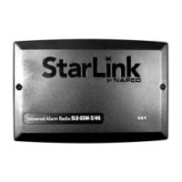
SLE-GSM-3/4G - 2G, 3G and 4G Network Compatible
GSM alarm capture Communicator, SIM card included.
Black plastic enclosure.
SLE-GSM-8D-3/4G - 2G, 3G and 4G Network Compatible
GSM alarm capture Communicator. Supports remote
downloading to the Gemini GEM-P400, GEM-P800,
GEMP-801, Express XP-400 and XP-600 series control
panels. SIM card included. Black plastic enclosure.
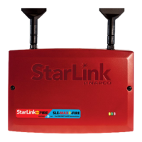
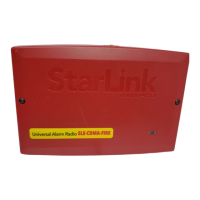
SLE-CDMA - Universal CDMA alarm capture Communica-
tor. Black plastic enclosure.
SLE-CDMA-8D - Universal CDMA alarm capture Commu-
nicator. Supports remote downloading to the Gemini
GEM-P400, GEM-P800, GEMP-801, Express XP-400
and XP-600 series control panels. Black plastic enclo-
sure.
ADDITIONAL COMPONENTS
In addition to the models listed above, the following sub-
assemblies are available:
SLE-DLEXT - Optional, for up/downloading, extends dis-
tance from radio to panel, from 10 feet, up to 100 feet.
See installation instructions WI1950.
SLE-DLCBL - Download Cable, 6 feet.
SLE-SMTCHG - Smart Charge Module, optional charger /
power supply.
SLE-ANTEXT - Extended antenna with 15 feet of cable.
SPECIFICATIONS
The following specifications apply to all StarLink radio mod-
els unless otherwise stated:
Electrical Ratings for +12V (all models powered by the
control panel)
Input Voltage: 15-10.6VDC
Input Current: 65mA with peak RF transmission current of
400mA for models SLe-GSM-3/4G and SLE-CDMA; (80mA
with peak RF transmission current of 400mA for model SLe
-GSM-8D-3/4G and SLE-CDMA-8D)
WI1936E 12/14
333 Bayview Avenue
Amityville, New York 11701
For Sales and Repairs, (800) 645-9445
For Technical Service, (800) 645-9440 or visit us at
http://tech.napcosecurity.com/
(Note: Technical Service is for security professionals only)
Publicly traded on NASDAQ Symbol: NSSC
© NAPCO 2014
INTRODUCTION
The StarLink
™
alarm capture radio communicators are fully
supervised, wireless digital two-way subscriber units sup-
ported by an extensive nationwide wireless network. All
models are compatible with virtually any 12VDC alarm con-
trol panel and are easy to install and test (always adhere to
the documentation provided by the control panel manufac-
turer). All can function as a backup to existing telephone
lines, or as a primary communicator when telephone lines
are absent and when connected directly to the control pan-
el Telco terminals. When used as a backup communicator,
all units will automatically switch the communication chan-
nel from the telephone line to the network when telephone
line trouble is detected.
The StarLink radio communicators use proprietary data-
capture technology that captures the alarm report from the
control panel and transmits the alarm signals to the SLE
Control Center; the alarm signals are then forwarded to
ANY Central Station via standard CS receiver formats 4/2
( ( ( ( ( ( ( ( ( ( ) ) ) ) ) ) ) ) ) )
(1)
(2)
Control
Panel
Network
Operator
SLE Control Center
(3)
CENTRAL
STATION
(5)
(4)
RADIO REPORTING PATH
The diagram below shows the transmission path of a
signal from the radio to the central station.
1. Signal from a Control Panel.
2. StarLink radio receives the signal
transmission (from the TIP an RING wires); sends
RF signal through the network operator.
3. Network Operator, part of the vendor system,
a section of the cellular spectrum.
4. SLE Control Center (NOC), receives and
routes data.
5. Central Station.
StarLink
Radio
StarLink™ SLE Series
Alarm Communicators
INSTALLATION INSTRUCTIONS


 Loading...