EasyManua.ls Logo

NAPCO StarLink SLE User Manual

NAPCO StarLink SLE
24 pages
To Next Page IconTo Next Page
Page #1 background imageLoading...
Page #1 background image
StarLink
SLE Commercial Series Alarm Communicators -- Installation Instructions 1
Control Center reports a trouble signal in the event that the
network does not receive the expected supervision signal
from the wireless communicator. In addition, all models
are powered directly from the control panel.
For Commercial Burglary installations, under the
armed condition, any loss of communication must be
treated as a Burglary Alarm at the Central Station.
The model names are as follows:
SLE-GSM-3/4G - Commercial / Residential Burglary and
Residential Fire 2G, 3G and 4G Network Compatible
GSM alarm capture Communicator, SIM card included.
Black plastic enclosure.
SLE-GSM-8D-3/4G - Commercial / Residential Burglary
and Residential Fire 2G, 3G and 4G Network Compati-
ble GSM alarm capture Communicator. Supports re-
mote downloading to the Gemini GEM-P400, GEM-
P800, GEMP-801, Express XP-400 and XP-600 series
control panels. SIM card included. Black plastic enclo-
sure.
SLE-CDMA - Commercial / Residential Burglary and Resi-
dential Fire Universal CDMA alarm capture Communica-
tor. Black plastic enclosure.
SLE-CDMA-8D - Commercial / Residential Burglary and
Residential Fire Universal CDMA alarm capture Com-
municator. Supports remote downloading to the Gemini
GEM-P400, GEM-P800, GEMP-801, Express XP-400
and XP-600 series control panels. Black plastic enclo-
sure.
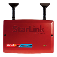
SLE-GSM-FIRE - Commercial / Residential Fire and Bur-
glary 2G, 3G and 4G Network Compatible GSM alarm
capture Communicator. SIM card included. Red plastic
enclosure.
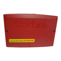
SLE-CDMA-FIRE - Commercial / Residential Fire and Bur-
glary CDMA radio in red plastic enclosure.
ADDITIONAL COMPONENTS
In addition to the models listed above, the following sub-
assemblies are available:
SLE-DLCBL - Download Cable, 6 feet.
SLE-ANTEXT - Extended antenna with 15 feet of cable.
WI2120.a 04/15
333 Bayview Avenue
Amityville, New York 11701
For Sales and Repairs, (800) 645-9445
For Technical Service, (800) 645-9440 or visit us at
http://tech.napcosecurity.com/
(Note: Technical Service is for security professionals only)
Publicly traded on NASDAQ Symbol: NSSC
© NAPCO 2015
INTRODUCTION
The StarLink
Commercial / Residential Fire and Burglary
alarm capture radio communicators are fully supervised,
wireless digital two-way subscriber units supported by an
extensive nationwide wireless network. All models are
compatible with most 12VDC alarm control panels (always
adhere to the documentation provided by the control panel
manufacturer). All can function as a backup to existing tel-
ephone lines, or as a primary communicator. In backup
mode, all units will automatically switch the communication
channel from the telephone line to the network when tele-
phone line trouble is detected. For Commercial installa-
tions, mount the unit to a single-, dual-, or three-gang elec-
trical box and route the wires through the back knockout(s),
or as specified by local codes. See WI2140 for program-
ming information.
The SLE Series radios use proprietary data-capture tech-
nology that captures the alarm report from the control panel
and transmits the alarm signals to the SLE Control Center;
the alarm signals are then forwarded to ANY central station
via Contact ID or Sur-Gard System II via TCP/IP. The SLE
STARLINK RADIO REPORTING PATH
The diagram below shows the transmission path of a
signal from the StarLink radio to the central station.
1. Signal from a Control Panel.
2. StarLink radio receives the signal transmission
(from the TIP an RING wires); sends RF signal
through the GPRS network operator.
3. Network Operator, part of the vendor system, a
section of the cellular spectrum.
4. SLE Control Center, receives and routes data.
5. Central Station.
( ( ( ( ( ( ( ( ( ( ) ) ) ) ) ) ) ) ) )
(1)
(2)
Control
Panel
Network
Operator
StarLink Network
Operations Center
(3)
CENTRAL
STATION
(5)
(4)
StarLink
Radio
StarLink™ SLE
Residential / Commercial Series
Alarm Communicators
INSTALLATION INSTRUCTIONS
AGENCY LISTINGS
 UL 864 Standard For Control Units and Accessories For Fire
Alarm Systems, 9th Edition
 UL 1610 Standard For Central-Station Burglar-Alarm Units
 UL 985 Standard For Household Fire Warning System Units
 UL 1023 Standard For Household Burglar-Alarm System
Units
CDMA models are Verizon
®
Network Certified

Table of Contents

Question and Answer IconNeed help?

Do you have a question about the NAPCO StarLink SLE and is the answer not in the manual?

NAPCO StarLink SLE Specifications

General IconGeneral
Power Supply12VDC
NetworkGSM
EnclosurePlastic
AntennaInternal
CertificationsFCC, UL
Standby Time24 hours
Additional FeaturesRemote control

Summary

INTRODUCTION

SLE-GSM-3/4G Models

GSM/GPRS communicator, supports remote downloading.

SLE-GSM-8D-3/4G Models

Enhanced GSM/GPRS communicator, supports remote downloading for specific panels.

SLE-CDMA Models

CDMA communicator, universal.

SLE-CDMA-8D Models

Enhanced CDMA communicator, supports remote downloading.

SLE-GSM-FIRE Models

GSM/GPRS communicator for fire alarms.

SLE-CDMA-FIRE Models

CDMA communicator for fire alarms.

STARLINK RADIO REPORTING PATH

Signal Path Overview

Describes the signal transmission path from control panel to central station.

ADDITIONAL COMPONENTS

SLE-DLCBL

Download Cable, 6 feet.

SLE-ANTEXT

Extended antenna with 15 feet of cable.

AGENCY LISTINGS

SPECIFICATIONS

Electrical Ratings

Details input voltage, current, and loop ratings for various models.

Physical and Environmental

Covers unit dimensions, housing, operating temperature, and humidity.

TERMINAL DESCRIPTIONS

Power and Ground Terminals (TB1-TB2)

Describes the +12V and Ground power input terminals.

Programmable Output Terminals (TB3-TB5)

Details PGM1, PGM2, and PGM3 open collector output functions.

Input Terminals (TB6-TB9)

Explains IN1, IN2, GND, and IN3 terminal functions for inputs.

NOTICE TO AUTHORITIES HAVING JURISDICTION, USERS, INSTALLERS, DEALERS, AND OTHER AFFECTED PARTIES

LED LOCATIONS

Red Diagnostic LED (D7)

Location of the Red Diagnostic LED on the PC board.

Yellow Operational Status LED (D4)

Location of the Yellow Operational Status LED on the PC board.

Green RF Signal Strength LED (D3)

Location of the Green RF Signal Strength LED on the PC board.

LED DESCRIPTIONS

Green RF Signal Strength LED Operation

Explains how the Green LED indicates signal strength.

Radio Receiver Coverage Table

Table correlating LED blinks to RF signal strength (dBm).

Yellow Operational Status LED Operation

Describes the operational behavior of the Yellow LED.

RED TROUBLE LED

Trouble Blink Codes

Lists blink codes for various trouble conditions detected by the Red Trouble LED.

RED DIAGNOSTIC LED

Diagnostic LED Behavior

Describes the behavior of the Red Diagnostic LED for signal issues.

SUPPLYING POWER

Power Supply Options

Explains power options and the need for the SLE-ULPS-R accessory.

JUMPER DESCRIPTIONS

Jumper Block X5 Configuration

Details the function of jumpers in block X5 for various settings.

PRIMARY AND BACK-UP REPORTING

Reporting Modes

Explains how the radio functions as primary or backup communicator.

NETWORK COVERAGE

GPRS Network Supervision

Describes the radio's supervision of GPRS network coverage.

INSTALLATION STEPS

Step 1: Account Registration

Guide to creating an account and registering modules online.

Step 2: Mounting Location Selection

Recommendations for choosing an optimal mounting location for RF performance.

Cover Tamper

Front Tamper Switch Functionality

Describes the front tamper switch on the radio housing.

SIGNALS ORIGINATED AT THE NOC

PRIMARY AND BACK-UP REPORTING WIRING

Primary Mode Wiring Configuration

Wiring diagram and instructions for primary reporting.

Backup Mode Wiring Configuration

Wiring diagram and instructions for backup reporting.

Wiring Methods

General Wiring Practices

Guidelines for proper wire stripping and insulation.

STEP 4: APPLY POWER

Power Requirements

Details the 12VDC power requirement and current draw.

STEP 5: SIGNAL VERIFICATION

Verify Online Status

Instructions to verify radio status via the NapcoComNet website.

Central Station Verification

Importance of verifying signals received by the central station.

CONTROL PANEL PROGRAMMING

Central Station Receiver Configuration

Guide to configuring the central station receiver format.

Point ID Receiver Example

Example of Point ID (Contact ID) receiver format programming.

SIA/DSC Sur-Gard Transmission

Capabilities for transmitting SIA Contact ID and DSC Sur-Gard.

Programming StarLink Radio Troubles

PGM1 Output for Trouble Reporting

How to use PGM1 output to annunciate radio troubles.

Wiring PGM1 to Napco Panels

Specific wiring for PGM1 with Napco control panels for trouble reporting.

StarLink Radio Supervision

Control Panel Trouble Detection

How control panels detect and report radio troubles.

Line Cut Feature Configuration

Enabling the Line Cut feature via advanced settings.

Supervision Time Schedule Considerations

Supervision Timer Restart

How status changes affect the radio supervision timer.

Configuration Download / Firmware Updates

Technician On-Site Requirement

Necessity of a technician for downloads/updates.

Jumper 1 for Firmware Updates

Role of Jumper 1 in firmware update procedures.

IMPORTANT WIRING METHODS

Single-Conductor Terminal Blocks

Proper wiring for single-conductor terminals.

Barrier-Type Terminal Blocks

Proper wiring for barrier-type terminals.

Special Wiring Instructions for GEMC-F8ZCPIM

PGM1 as Monitor Zone

Special wiring for PGM1 when used with GEMC-F8ZCPIM zone.

PGM2/PGM3 as Monitor Zone

Special wiring for PGM2/PGM3 with GEMC-F8ZCPIM zones.

NAPCO LIMITED WARRANTY

Warranty Terms and Duration

Outlines the 36-month warranty period and coverage.

Warranty Exclusions

Lists conditions that void the warranty.

Liability Limitations

Details limitations on consequential and incidental damages.

Installer and Consumer Responsibilities

Defines roles for warranty claims and system testing.

Related product manuals