StarLink
™
SLE Commercial Series Alarm Communicators -- Installation Instructions 7
the control panel generates a trouble that is sent to the cen-
tral station.
All installations also require wiring an output from the con-
trol panel, as follows: With Gemini C-Series (GEMC) con-
trol panels, we recommend using the Fire Aux Relay. Pro-
gram the Fire Aux Relay to activate as a trouble relay. Wire
this zone to the StarLink module IN2 terminal. Note: We
recommend using the text "GSM Trouble" as the Zone De-
scription.
StarLink Radio Supervision
If the two Telco wires between the StarLink radio and the
control panel are cut or otherwise disconnected, the control
panel must detect and generate a local trouble indication.
The control panel must trigger an output to activate the
StarLink radio to report this line cut fault to the central sta-
tion. Program the control panel for telephone supervision.
Program the StarLink radio using the Management Center
"Advanced Features" screen (at www.napconoc.com) to
enable the Line Cut feature on all troubles (therefore a dedi-
cated zone is not required). Note: Some control panels
may require a different duration than the default time of 3
minutes.
Supervision Time Schedule Considerations
If a status change (alarm trouble, etc.) is transmitted, the
radio supervision timer is restarted.
For example, if a status change is sent, the next regular
supervision transmission will occur at the interval deter-
mined by your rate plan.
Configuration Download / Firmware Updates
Technician on site required.
To perform a download or update the radio firmware, jump-
er 1 must be removed. UL requires that the jumper be re-
placed after the download is complete. Failure to replace
the jumper would allow downloads to the radio without
a technician on-site.
page 5. Note: These event codes and zone numbers can
be changed from the Management Center screen (located at
www.napconoc.com).
Upon alarm, the NOC can optionally send an SMS message
to a third party that includes the appropriate Contact ID
alarm code, including the zone or user number, if applicable.
The "STARLINK RADIO RELATED EVENT REPORT
CODES" table includes the most common Contact ID alarm
codes.
Programming StarLink Radio Troubles
It is required that if a StarLink radio or control panel trouble
is detected, that it is reported to the central station.
When the StarLink radio detects and sends a trouble to the
control panel, the control panel must be programmed to
annunciate this trouble. The radio can detect multiple trou-
bles as indicated by the "Red Trouble LED" ("D5"). For
these troubles to be annunciated at the control panel, there
are several methods, some of them are configurable at the
Management Center screen (www.napconoc.com):
Wire the radio PGM1 output to a dedicated control panel
zone (input) to annunciate the trouble (activate a trouble
sounder) when an open is detected. The radio must also
report this trouble to the central station. With Napco control
panels, program a dedicated zone for Day Zone, Mini-
sounder on Alarm and No bell on Alarm. Wire the zone as
indicated in the wiring diagrams further in this manual.
For radio models powered by the control panel Aux Power
terminals, wire the radio directly to the PGM1 output of the
control panel (program the radio to report all troubles on
PGM1). Alternatively, you can use the GEMC-F8ZCPIM
module to detect a trouble on the zone by use of a PGM
output of the radio. See special wiring instructions for use
of the GEMC-F8ZCPIM zones.
You can also wire to the positive terminal of the dedicated
zone on a GEMC-EZM8. Thus when a radio trouble is de-
tected, the radio PGM activates the control panel zone, and
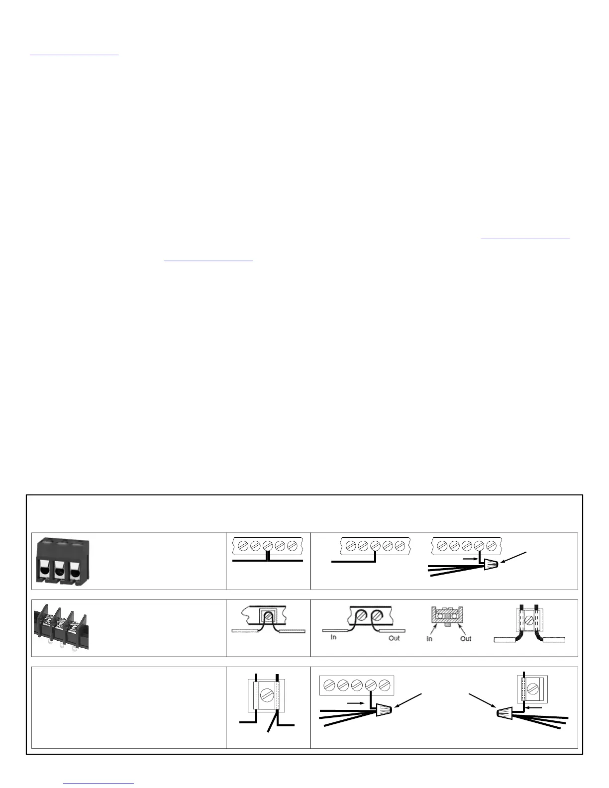
To terminate more than two conductors or
conductors of different wire sizes to a terminal,
use the "pigtail" type wiring method as shown at
right. Use insulated wire for the pigtail, and firmly
secure the conductors to the pigtail using an ap-
propriate wire nut or crimp connector for the num-
ber and gauge of conductors used.
IMPORTANT WIRING METHODS
Incorrect
Correct -- Use pigtail and wire nut / crimp connector
PIGTAIL
WIRE NUT OR
CRIMP
CONNECTOR
PIGTAIL
For single-conductor terminal
blocks (like the type shown at
left), to terminate more than one
conductor to a terminal, use the
wiring methods shown at right:
WIRE NUT OR
CRIMP
CONNECTOR
PIGTAIL
Correct -- Single incoming and/or pigtail with wire nut / crimp connectors
In
For "barrier" type terminal
blocks (like the type shown at
left), to terminate two conductors
to a terminal, use the wiring meth-
ods shown at right:
Correct -- Separate incoming and outgoing conductors
In Out
Incorrect
Incorrect
In
Out

 Loading...