10 StarLink
™
SLE Commercial Series Alarm Communicators -- Installation Instructions
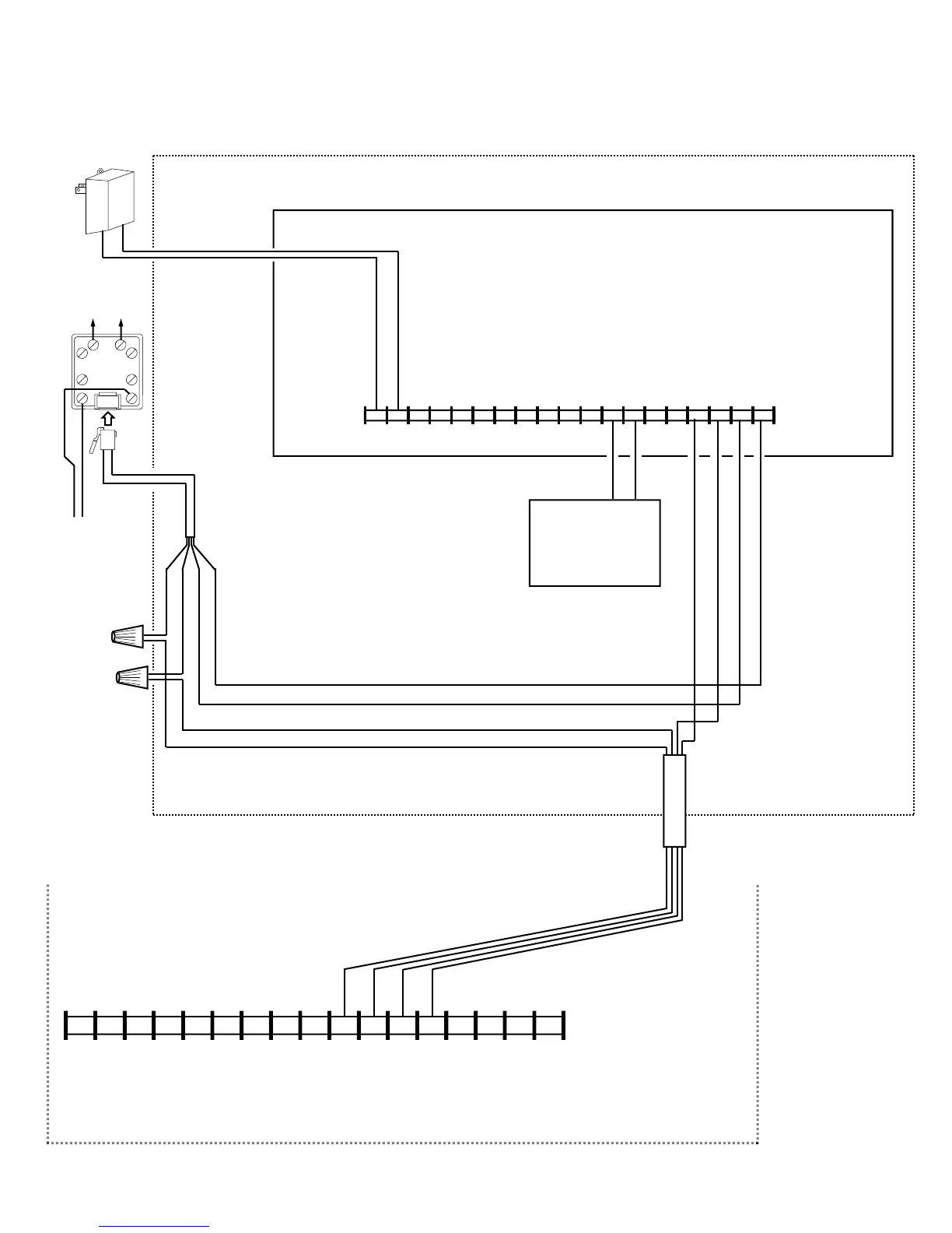
Wiring Diagram for BACKUP Reporting Configuration
GEM-P400 / GEM-P800 / Express XP-400 / Express XP-600 Control Panels
CONTROL PANEL PC BOARD
GRN
RED
BRN
GRAY
(CONTROL PANEL HOUSING)
GRN
RED
YELLOW
BLACK
6 7 8
17 16 15 14 13 12 11
9
10 2
3 4 5
1
19 18
16VAC
*For StarLink termi-
nals 1 and 2: May
be wired directly to
Aux Power of the
control panel when
65mA standby
current is available
HOME
PHONES
TO TELCO
RJ31X
RING TIP
(–) (+)
AUX POWER
(RING)
(TIP)
(RING)
(TIP)
(TELCO) (PHONE)
YELLOW (–)
BLACK (+)
*Refer to section "SUPPLYING POWER".
6 7 8 15 14 13 12 11 9 10 2* 3 4 5 1*
+12V
(–)
PGM1 PGM2 PGM3 IN1 IN2 GND IN3 RING TIP
17 16
RTS
(R)
PANEL
TX (B)
PANEL
RX (G)
CTS
Y
StarLink Radio Terminals
PANEL
RING (+)
PANEL
TIP (–)
(STARLINK RADIO HOUSING)
16VAC
Transformer
TELCO QUAD WIRE
Optional: When Power
Supply SLE-ULPS-R is not
used, connect Panel Aux
Power to StarLink terminals
1 and 2 (observing polarity)
All connections are
power limited ex-
cept AC Mains, Tel-
co and battery ter-
minals. Terminals
14-17: No connec-
tions permitted.

 Loading...