8 StarLink
™
SLE Commercial Series Alarm Communicators -- Installation Instructions
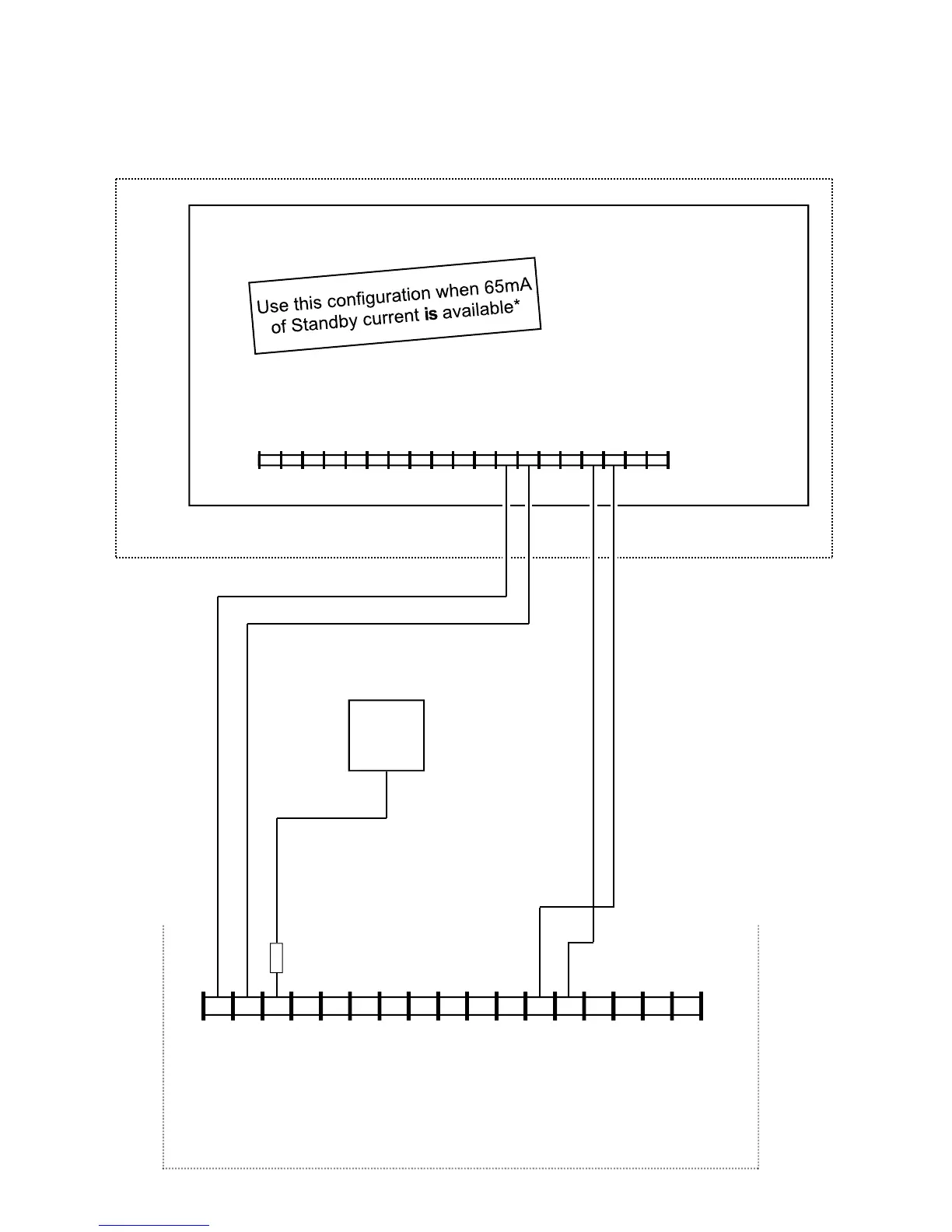
Wiring Diagram for PRIMARY Reporting Configuration
GEM-P400 / GEM-P800 / Express XP-400 / Express XP-600 Control Panels
(Use when telephone line is NOT available)
CONTROL PANEL PC BOARD
6 7 8
17 16 15 14 13 12 11
9
10 2
3 4 5
1
19 18
ZONE (+)
DEDICATED
TO GPRS
SUPERVISION
(CONTROL PANEL HOUSING)
6 7 8 15 14 13 12 11 9 10 2* 3 4 5 1*
+12V
(–)
PGM1 PGM2 PGM3 IN1 IN2 GND IN3 RING
PANEL
RING (+)
TIP
2.2K
17 16
PANEL
TIP (–)
RTS
(R)
PANEL
TX (B)
PANEL
RX (G)
StarLink Radio Terminals
(RING)
(TIP)
*Refer to section
"SUPPLYING
POWER".
CTS
Y
(–) (+)
AUX POWER
(–) (+)
(STARLINK RADIO HOUSING)
All connections are power limited except AC
Mains, Telco and battery terminals.
Terminals 14-17: No connections permitted.

 Loading...