14 StarLink
™
SLE Commercial Series Alarm Communicators -- Installation Instructions
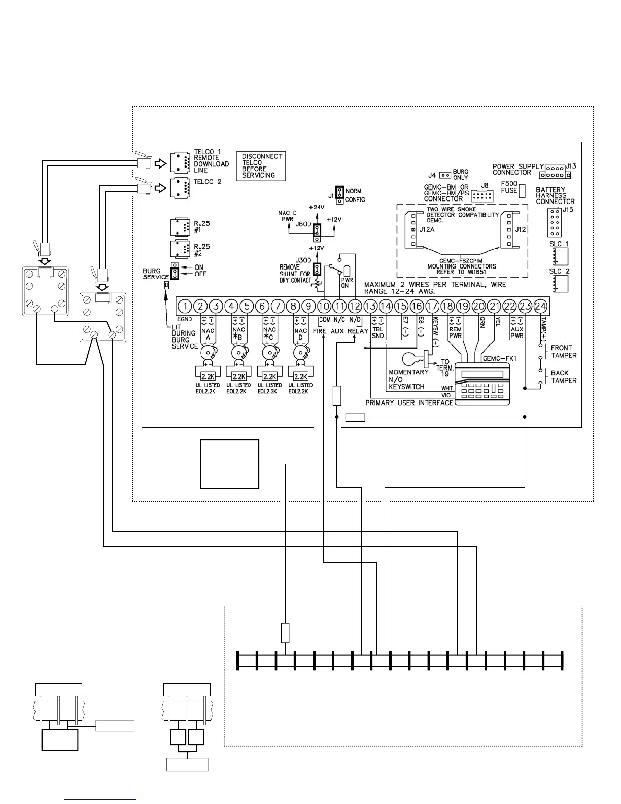
Wiring Diagram for PRIMARY Reporting Configuration
GEMC-32, GEMC-96, GEMC-128 and GEMC-255 Control Panels
(Use when telephone line is NOT available)
(CONTROL PANEL HOUSING)
RJ31X
RING TIP
GEMC Control
Panel PC Board
SEE WIRING
DIAGRAM
AND WI FOR
ADDITIONAL
INFORMATION
RJ31X
RING TIP
6 7 8 15 14 13 12 11 9 10 2* 3 4 5 1*
+12V
(–)
PGM1 PGM2 PGM3 IN1 IN2 GND IN3 RING TIP
17 16
RTS
(R)
PANEL
TX (B)
PANEL
RX (G)
CTS
Y
StarLink Radio Terminals
*Refer to section
"SUPPLYING POWER".
PANEL
RING (+)
PANEL
TIP (–)
(STARLINK RADIO HOUSING)
MONITOR ZONE
(+) DEDICATED
TO GPRS
SUPERVISION
2.2K
All connections are power limited ex-
cept AC Mains, Telco and battery termi-
nals. Terminals 14-17: No connections
permitted.
COM
Special Wiring Instructions for the
GEMC-F8ZCPIM as a Monitor Zone Only
When PGM1 is wired to a GEMC-F8ZCPIM
zone, replace the 2.2k ohm EOL resistor with
a 560ohm 1/2 watt min EOL resistor. Connect
PGM1 to the negative terminal of the zone.
When PGM2 and/or PGM3 are wired to a
GEMC-F8ZCPIM zone, replace the 2.2k ohm
EOL resistor with two 1K ohm 1/4 watt min
EOL resistors. Connect the PGM wire to the
common wire of the two resistors in series.
GEMC-F8ZCPIM
ZONE
EOLR
1K
Ω
Radio PGM2 or
PGM3 terminal
EOLR
1K
Ω
GEMC-F8ZCPIM
ZONE
(+)
(‒)
EOLR 560Ω
(min 1/2W)
Radio PGM1 terminal
10K
TELCO TROUBLE OUTPUT
10K

 Loading...