10 StarLink SLE-MAX2-FIRE Commercial Series Sole/Dual-Path Alarm Communicator -- Installation Instructions
F ACP P C B O AR D
LOCAL
DOWNLOAD
TELCO
SECONDARY
TELCO
PRIMARY
ETHERNET
1
(+)
2
(‒)
POWER PGM3 IN1 IN2 IN3
3
(‒)
4
(+)
5
(+)
6
(‒)
8
(‒)
7
(+)
9
(+)
10
(‒)
12
(‒)
11
(+)
13
EGND
19
N/O
21
N/C
20
C
IN4 IN5
OUT1
22
N/C
24
N/O
23
C
OUT2
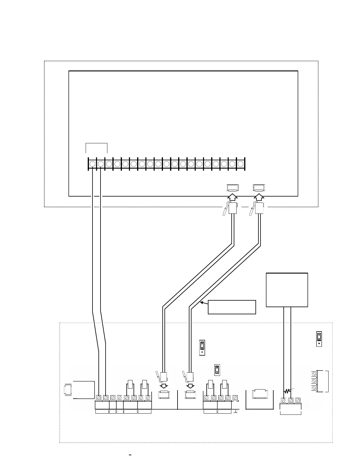
Wiring Diagram for Generic FACPs
with TELCO RJ Sockets
Refer to section
"SUPPLYING POWER".
Note: Optionally
connect IN2 to a
panel output used for
identifying Telco line
cut (this is the DACT
interconnect wiring to
the communicator).
(+) (‒)
(STARLINK COMMUNICATOR HOUSING)
StarLink Communicator Terminals
PC Board: All connections are power limited except battery terminals.
Optional: Use 12 or
24VDC Certified regu-
lated power supply*.
Note: Common com-
municator ground and
FACP ground.
(CONTROL PANEL HOUSING)
TELCO RJ
SOCKET
(PRIMARY)
10kΩ
10kΩ
10kΩ
TELCO RJ
SOCKET
(SECONDARY)
10kΩ
To FACP Zone
Dedicated to
Communicator
Trouble*
EOLR
Requires all 8 wires in
the RJ-45 cable
JP1
Shunt JP1
on top 2 pins
JP2
Remove JP2 to
enable TELCO2
trouble on
Communicator trouble
*Not required if JP2 shunt is removed and FACP monitors TELCO 2.
AUX / REMOTE
FIRE PWR
J7
J7: Remove shunt to
disable 10K EOLR
across pins 1 and 8 of
primary TELCO input.
Do not remove if "Tip/
Ring Wiring Fault
Report" is enabled.

 Loading...


