StarLink SLE-MAX2-FIRE Commercial Series Sole/Dual-Path Alarm Communicator -- Installation Instructions 3
Note: Inputs IN 2, IN 3, IN 4 and IN 5 can be super-
vised end-of-line resistor inputs that can be triggered
with N/O or N/C relay contacts.
TB6: IN 2 (–): See TB5, above.
TB7: IN 3 (+): Fire Alarm input**. Wire to FACP Fire Alarm
relay N/O with parallel 10K EOLR at FACP.
TB8: IN 3 (–): See TB5 and TB7, above.
Secondary Telephone: RJ-45 socket for FACP DACT con-
nection.
Primary Telephone: RJ-45 socket for FACP DACT connec-
tion.
TB9: IN 4 (+): Supervisory Alarm input**. Wire to FACP
Supervisory relay N/O with parallel 10K EOLR at
FACP.
TB10: IN 4 (–): See TB5 and TB9, above.
TB11: IN 5 (+): Water Flow Alarm input**. Wire to FACP
Water Flow relay with parallel 10K EOLR at FACP.
TB12: IN 5 (–): See TB5 and TB11, above.
TB13: GND: Earth ground terminal.
NOTICE TO AUTHORITIES HAVING JURISDICTION, USERS, INSTALLERS, DEALERS, & OTHER AFFECTED PARTIES
FIRE PROGRAMMING OPTION
PERMITTED IN
UL864? (Y/N)
AVAILABLE SETTINGS REQUIRED UL 864 SETTINGS
Unattended Remote Downloading No Enable / Disable
Disabled (Jumper 1 installed). Also required for Commercial installations. Note: See
page 7 "Configuration Download / Firmware Updates" for jumper instructions.
4/2 Pulse Dialing Format
'No' for UL864 10th
Edition FACP
Jumper ON / OFF (see page
5 Jumper Descriptions)
Not for use with FACP Certified to UL 864 10th Edition unless authorized by the AHJ.
IN2 and IN3 Unsupervised Yes Supervised / Unsupervised
Unsupervised using conduit within 20 feet of FACP (default). If not using conduit, install
Jumpers 4 and 5 and EOL Resistors. Inputs 2 an 3 can be unsupervised with jumpers 4
and 5 removed; IN4 and IN5 always require EOLR.
7 Day Supervision, Communicator to
NOC
No
200 seconds, 5 minutes, 6
minutes, 60 minutes, 6 hours,
7 days
200 seconds, 5 minutes, 6 minutes (Dual-Path Commercial Burglary), 60 minutes. 6
Hours permitted in Commercial Fire UL 864 with Dual Path enabled (6 hour dual-cell
carrier is for Commercial Fire only)
Trouble on Communicator or IP Path
(Annunciate / Report)
Yes Either Path or Both Paths Either Path (annunciation and report of trouble).
Wi-Fi Module Yes Enable / Disable May be enabled as a primary reporting path for Fire.
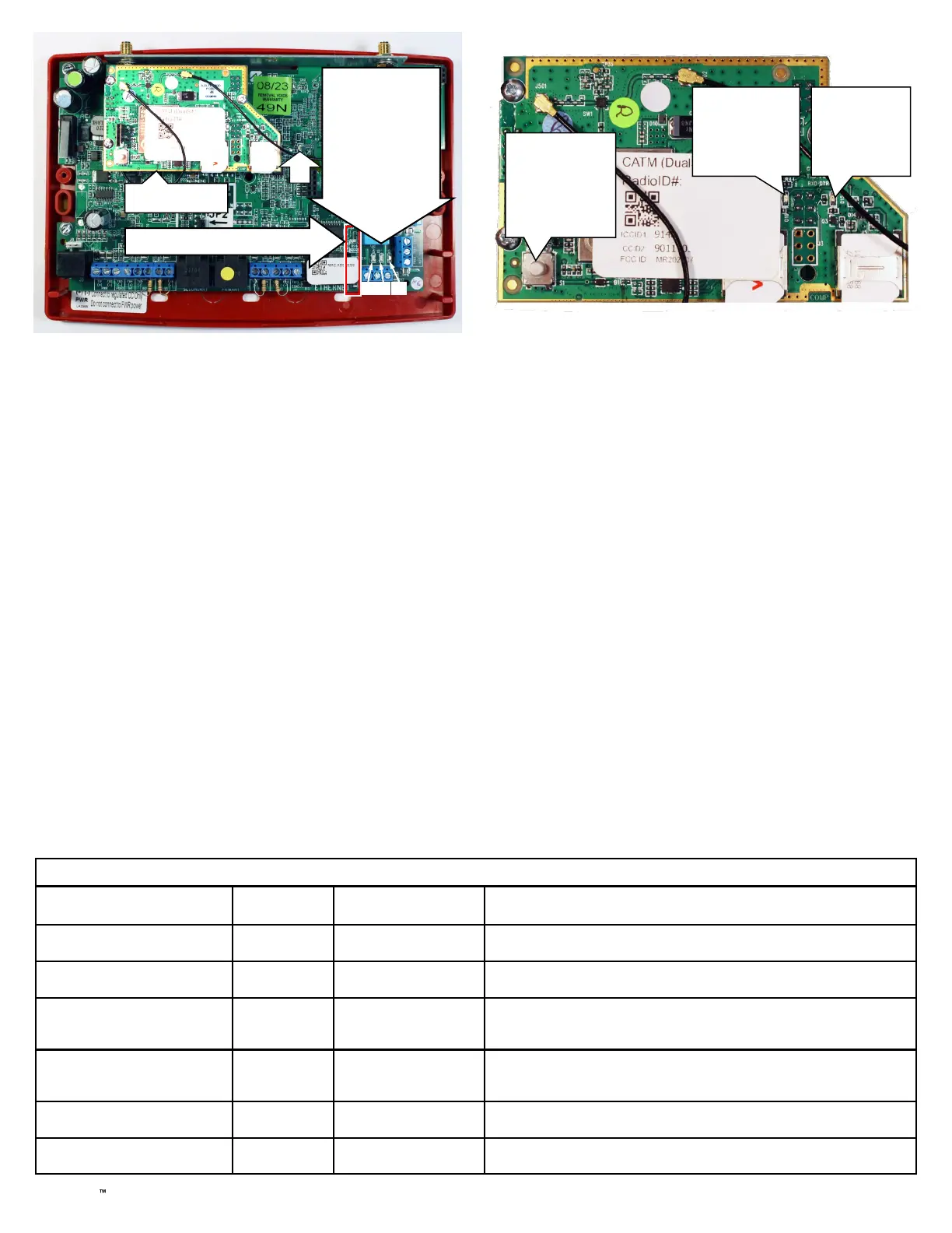
Radio PCB: Illuminated LED indicates carrier in use.
IP Communication LEDs
D4 D3 D5
• YELLOW
OPERATIONAL
STATUS LED ("D4")
• GREEN RF SIGNAL
STRENGTH LED
("D3")
• RED TROUBLE LED
("D5")
LED LOCATIONS (See image at right for close-up of Radio PCB )
LED "D7" is the "RED DIAGNOSTIC LED" (see page 4)
Push button
to toggle
between
carriers
Verizon
Active when
lit
(Red LED)
AT&T
Active
when lit
(Blue LED)
Radio PCB
D7
Ethernet: Connect the SLE Sole/Dual-Path communicator to
your broadband modem, router or switch for dual path
operation. Note: The cable modem/router and switch
(if any) at the premises requires standby power, there-
fore a UL 1481 / UL 864 or UL Certified ITE
(Information Technology Equipment) UPS must be
used at the premises to power these devices for a
minimum of 24 hours.
TB19: N/O OUT1: Normally open. Dry contact Form C re-
lay. Add shunt to lower two pins of JP1 for wet con-
tacts.
TB20: C OUT1: Common. Dry contact Form C relay. Add
shunt to lower two pins of JP1 for wet contacts
(connects relay Common to system ground). Relay
rated 30V AC/DC, 500mA.
TB21: N/C OUT1: Normally closed. Dry contact Form C
relay. Add shunt to lower two pins of JP1 for wet con-
tacts.
TB22: N/O OUT2: Normally open. Dry contact Form C re-
lay.
TB23: C OUT2: Common. Dry contact Form C relay. Relay
rated 30V AC/DC, 500mA.
TB24: N/C OUT2: Normally closed. Dry contact Form C
relay.

 Loading...


