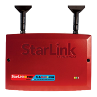
4 StarLink SLE-MAX2-FIRE Commercial Series Sole/Dual-Path Alarm Communicator -- Installation Instructions
RED DIAGNOSTIC LED
Labeled "D7", this LED is located in the middle of the PC
board. One blink indicates a weak or non-existent signal
from the network (green LED is off). If this red LED is blink-
ing in any other manner, please contact technical support.
GREEN IP NETWORK CONNECTION LED
Labeled "D14" (or DS14), this LED is located to the right of
the ETHERNET socket on the PC board. Operation is as
follows:
Off = No network cable detected
Fast Flash = No IP connection (Occurs just after power
on, while trying to obtain a IP address)
Slow Flash = Normal IP network operation
• 1 Blink: Static IP
• 2 Blinks: DHCP
• 3 Blinks: Auto IP (if unable to acquire DHCP address,
then after 5 minutes it will convert to Auto IP)
RED IP NETWORK TROUBLES LED
Labeled "D16" (or DS16), this LED is located to the right of
the ETHERNET socket on the PC board. Operation is as
follows:
Off = No troubles
Fast Flash = No IP connection (occurs just after power on
while trying to obtain a DHCP address)
Slow Flashing:
• 1 Blink: No network cable detected
• 2 Blinks: No access to the Internet
• 3 Blinks: Ethernet failed to communicate
• 4 Blinks: Ethernet poll / checkin fail
• 5 Blinks: Wi-Fi is enabled, but SLE-WIFI-MODULE is
not detected
• 6 Blinks: Wi-Fi no access to the Internet
• 7 Blinks: Wi-Fi failed to communicate
• 8 Blinks: Wi-Fi poll / checkin failure
• 9 Blinks: Wi-Fi serial data error or no serial data re-
sponse
• 10 Blinks: Wi-Fi Security / Authentication failed
YELLOW IP NETWORK STATE LED
Labeled "D15" (or DS15), this LED is located to the right of
the ETHERNET socket on the PC board. Operation is as
follows:
Off = No power
Steady with 1 quick blink off every 1.7 seconds when
reporting signal to NOC
Steady with 2 quick blinks off every 1.7 seconds when
downloading to control panel or the module
Slow Flashing:
• 1 Blink: Ethernet Available
• 2 Blinks: Wi-Fi Station Mode (normal operation)
RED / BLUE RADIO CARRIER PCB LEDs
On top of the main PC board, a smaller radio PC board is
mounted that includes an LED next to each SIM card slot
(see page 3 for image). When lit, the LED next to the SIM
card slot indicates the currently active slot (blue LED for
AT&T and red for Verizon). Note: The yellow LED (D4)
on the main PCB indicates a SIM scan is in progress. See
YELLOW OPERATIONAL STATUS LED on page 3.
LED DESCRIPTIONS
The main PC board contains several LEDs, as follows:
GREEN RF SIGNAL STRENGTH LED
Labeled "D3", this LED is located at the lower right corner
of the PC board.
Every 30 seconds, the StarLink communicator receiver
section turns on and listens to the cell tower. Depending
on the signal strength detected, it will blink the Signal
Strength LED from 1 to 5 times, providing a signal strength
indicator that is updated constantly and is always dis-
played.
Green LED Operation
Signal strength (as received by the communicator) is dis-
played by this LED blinking 1 to 5 times at a constant rate
(with a short delay between blink cycles). Acceptable
power level is greater than or equal to 2 blinks.
YELLOW OPERATIONAL STATUS LED
Labeled "D4", this LED is located at the bottom right of the
PC board. Operation is as follows:
Normal Standby Condition:
• Blinks on momentarily every 10 seconds: Unit is in
standby waiting for an alarm to report.
Processing Alarm Conditions:
• When processing an alarm, this LED will blink variably
during each part of the process (dialing, handshaking,
data transmission, etc.).
Scanning Each SIM Carrier for Signal Quality
Switching from One SIM to the Other:
• Blinks at the rate of one second on, one second off.
The unit is scanning each SIM slot and selects the carri-
er with the best signal quality. Also if the radio PCB is
equipped with a momentary pushbutton, press/release
this button to switch between SIMs. See page 3 and 8
for more information.
RED TROUBLE LED
Labeled "D5", this LED is located at the bottom right of the
PC board. Operation is as follows:
• 1 Blink: Low Aux Power input voltage
• 2 Blinks: Check Input Power
• 3 Blinks: Alarm report Failed to Communicate (will re-
store only when the communicator path is restored)
• 4 Blinks: RF trouble (antenna connection or cellular
registration)
• 5 Blinks: Communicator poll or check-in failure (cellular
and/or IP). Either or both paths will trigger the trouble,
but for the trouble to clear, unit requires that the previ-
ously active path(s) must restore (i.e. cellular if used as
a Sole Path communicator, and both cellular and IP if
unit is used as a Dual Path communicator)
• 6 Blinks: Unit disabled (reporting or control panel
downloading not allowed). Power cycle the unit and if it
does not clear, then call for Technical assistance.
• 7 Blinks: Unit was shut down and has no functionality;
requires a restart (full power down and full power up
sequence) to restore operation
• 8 Blinks: Line Cut; check Telco and input wiring

 Loading...