StarLink SLE-MAX2-FIRE Commercial Series Sole/Dual-Path Alarm Communicator -- Installation Instructions 5
RADIO PC BOARD PUSHBUTTON (If Equipped)
If the radio PCB includes a momentary pushbutton, you can
press/release this button to manually switch from one SIM
slot to the other slot, and functions in the same way as the
Switch SIM button in the NOC's Radio Carrier screen. If
during normal operation the current slot is determined to be
non-functional, the other slot will automatically be used.
The status of both slots will be re-evaluated upon the next
scan. The LED color indicates the currently active carrier
(blue for AT&T and red for Verizon).
SUPPLYING POWER
Control panels can provide power through their Auxiliary/
Remote Fire Power terminals if the available standby current is
reduced by the SLE standby power (refer to Electrical Ratings
for +12V / 24V). Note: The cable modem/router and switch (if
any) at the premises requires standby power, therefore a UL
1481, UL 864 or ITE (Information Technology Equipment) Cer-
tified UPS must be used at the premises to power these devic-
es for 24 hours (unless an engine driven generator is provided
on the premises, then only 4 hours of UPS backup are re-
quired).
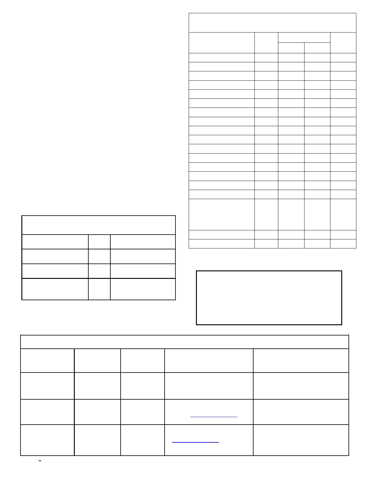
JUMPER DESCRIPTIONS
Jumper block labeled "X5"; from top to bottom, as detailed in
the following table. Note: Contact ID is always available in
response to a Contact ID handshake.
SI G N ALS O RI GI N AT ED A T T H E NO C
NOC Originated
Alarms
Contact ID
Event Data
Sent
Pulse Format
Event Code
Sent
Initiated By Comments
Supervisory Fail E356 A00 Zn000 99
Automatically by NOC if fail to receive
any signal from StarLink communicator
within Supervisory Timeout duration.
For Auto Enroll, uses captured telephone
number, Sub ID and format. For Dealer
Programmed, uses entered telephone
number, Sub ID and format.
Press to Send
Test Signal
E601 A00 Zn000 98
Manually by dealer from the Manage-
ment Center Signal Log screen
(located at www.NapcoNOC.com).
Sends test into CS receiver.
Same comment as above.
Press to Send
Communicator Test
Not Applicable
Nothing sent to
CS receiver
Not Applicable
Manually by dealer from the Manage-
ment Center Checkins screen (located
at www.NapcoNOC.com). Sends a
command to the StarLink communica-
tor to force a check-in to the NOC.
----
Jumper Block "X5" Options
Jumper block labeled "X5" contains 5 jumper terminals; from top (labeled
"1") to bottom (labeled "5") as follows:
Jumper ON
Jumper
Number
Jumper OFF
Tech on site must temporarily
remove to download
1 Not permitted by UL 864
4/2 with Checksum Pulse Format* 2
4/2 Pulse Format* (see table on
page 3)
Supervised inputs IN3 and IN2,
respectively.
EOLR(s) required, see pages 2-3
4 and 5
Not permitted by UL 864 (UL 864
permits use of conduit within 20
feet of FACP in lieu of
Supervision)
*See table "NOTICE TO AUTHORITIES HAVING JURISDICTION..." on page 3.
Cover Tamper
The communicators in the plastic housings are
provided with a front tamper switch. Note:
The tamper switch on the communicator PC
board is always functional and requires
programming if reporting to the central station.
STARLINK COMMUNICATOR RELATED EVENT
REPORT CODES (Contact ID by default)
EVENT AREA
CONTACT ID
PULSE
4/2**
CODE ZONE #
IN 1 Fire
0 E110 990 1A
IN 2 Trouble
0 E373 992 F2
IN 3 Fire
0 E110 993 1A
IN 4 Supervisory
0 E200 974 00
IN 5 Water Flow
0 E113 975 13
Low Battery/Voltage
0 E302 994 F4
Tamper Trouble
0 E341 995 F5
Reboot
0 E625 997 F7
IN 1 CO (Carbon Monoxide)
0 E162 998 18
Medical Alarm*
E100
24 hour Aux. Alarm*
E150
24 hour Aux. Restore*
R150
Keypad Emergency Alarm*
E140
A.C. Trouble*
E301
Tel 1 Fail*
E351
Fire Polling Report
E780 999 F9
Supv Failure Report
E788
Zone 1 for
radio/cell
path fail.
Zone 2 for
IP path fail
D1 or D2
Tip/Ring Wiring Fault Report
E789 000 F2
Path Test Report
E602 890 77
*Not generated by the StarLink communicator.
**See table "NOTICE TO AUTHORITIES HAVING JURISDICTION..." on page 3.

 Loading...


