StarLink SLE-MAX2-FIRE Commercial Series Sole/Dual-Path Alarm Communicator -- Installation Instructions 7
Wire the communicator OUT1 relay to a dedicated control
panel zone (input) to annunciate the trouble. Two wiring
options are available:
• Activate the trouble with an open by wiring the
EOLR in series with the Common and N/C of
the OUT1 relay;
• Activate the trouble with a short by wiring the
EOLR in parallel with the Common and N/O of
the OUT1 relay
The communicator must also report this trouble to the central
station. With NAPCO GEMC series control panels, wire the
zone as indicated in the wiring diagrams further in this manu-
al.
Optionally, the FACP trouble relay can be used to trigger a
report to the central station.
Wire the FACP trouble relay to IN2; Common and N/O ter-
minals in parallel with a 10K EOLR. With Gemini C-Series
(GEMC) control panels, we recommend using the Fire Aux
Relay. Program the Fire Aux Relay to activate as a trouble
relay. Wire this relay to the StarLink module IN 2 terminal;
by wiring the EOLR in parallel with Common and N/O of the
OUT1 relay. Note: We recommend using the text
"Communicator Trouble" as the Zone Description.
StarLink Communicator Supervision
If the two Telco wires (DACT interconnect wiring to the com-
municator) between the StarLink communicator and the con-
trol panel are cut or otherwise disconnected, the control pan-
el must detect and generate a local trouble indication. Pro-
gram the control panel for telephone supervision. Program
the StarLink communicator using the NOC Advanced Fea-
tures screen (at www.NapcoNOC.com) to enable Tip/Ring
Wiring Fault Report. Refer to wiring diagram.
Supervision Time Schedule Considerations
If a status change (alarm trouble, etc.) is transmitted, the
communicator supervision timer is restarted.
For example, if a status change is sent, the next regular su-
pervision transmission will occur at the interval determined
by your rate plan.
Configuration Download / Firmware Updates
Technician on site required.
For Commercial Installations a technician is required to be
on site during any reprogramming of the communicator or
control panel and must perform / re-perform acceptance
testing. To perform a download or update the communica-
tor firmware, jumper 1 must be removed. UL requires that
the jumper be replaced after the download is complete.
Failure to replace the jumper would allow downloads to
the communicator without a technician on-site.
For Residential installations jumper 1 may be removed to
permit uploading and downloading without a technician on
site, however, the dealer is responsible for ensuring the sys-
tem is operating correctly after any downloads or changes to
the system.
Commercial Burglary "Ringback"
Wire a sounder rated for the input voltage (12VDC or
24VDC) rated max 50mA @ 12VDC or 25mA @ 24VDC to
the positive input of the communicator and PGM3. See
WI2140 for information about how to use the NOC to pro-
gram PGM3 to activate on Ringback. Note: For Commer-
cial Burglary installations, only IP Receivers may be used.
particular installation. If this equipment does cause harmful
interference to radio or television reception, which can be de-
termined by turning the equipment off and on, the user is en-
couraged to try to correct the interference by one of more of
the following measures: 1. Reorient or relocate the receiving
antenna; 2. Increase the separation between the equipment
and receiver; 3. Connect the equipment into an outlet on a
circuit different from that to which the receiver is connected; 4.
Consult the dealer or an experienced radio/TV technician for
help.
NAPCO GEMINI C-SERIES (GEMC)
CONTROL PANEL PROGRAMMING
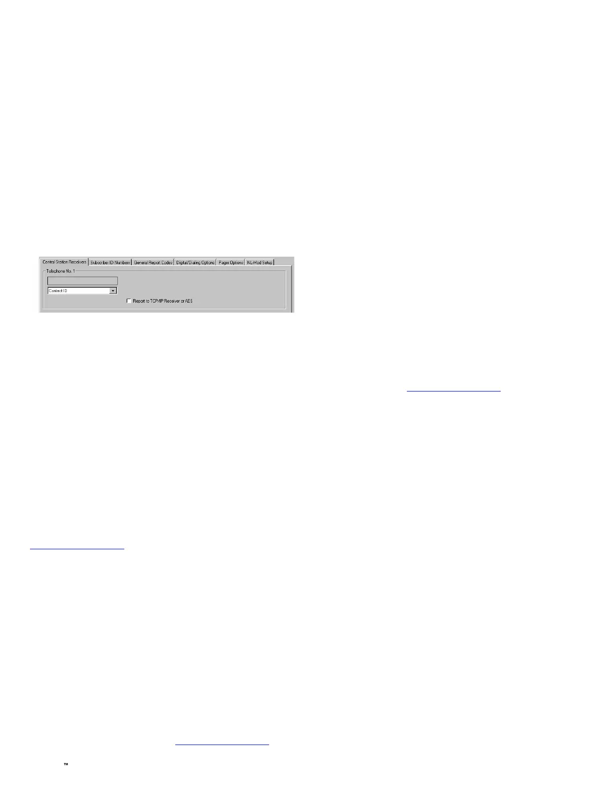
To program the central station receiver reporting format, use
PCD-Windows Quickloader download software. Open the
Digital Communications screen, Central Station Receiv-
ers tab, as shown in the following image:
A "Point ID" (also called "Contact ID") receiver format pro-
gramming example:
The communicator can transmit to any central station capa-
ble of receiving SIA Contact ID or 4/2 via DACR technology
or the DSC Sur-Gard Model System II or Sur-Gard System V
central station receivers, Bosch D6100IPV6 or Bosch D6600
Receiver (with ITS-D6686 Ethernet Adapter) via TCP/IP us-
ing standard line security.
Note: A receiver reporting format must be entered for each
telephone number used, but each telephone number may be
assigned a different format. If the NOC account is pro-
grammed for "Dealer Entered Programming," the receiver
formats must be the same.
CAUTION: The installer should always be certain an area
code is programmed into the control panel.
Optional: If you wish the StarLink communicator to report a
code and zone number (Contact ID by default) to the central
station in response to a triggered input event, see the table on
page 5. Note: These event codes and zone numbers can be
changed from the Management Center screen (located at
www.NapcoNOC.com).
Upon alarm, the NOC can optionally send an SMS message to
a third party that includes the appropriate Contact ID alarm
code, including the zone or user number, if applicable. The
"STARLINK COMMUNICATOR RELATED EVENT REPORT
CODES" table also includes the most common Contact ID
alarm codes.
Programming StarLink Communicator Troubles
It is required that if a StarLink communicator or control panel
trouble is detected, that it is reported to the central station.
When the StarLink communicator detects and sends a trouble
to the control panel, the control panel must be programmed to
annunciate this trouble. The communicator can detect multi-
ple troubles as indicated by the "Red Trouble LED" ("D5").
For these troubles to be annunciated at the control panel,
there are several methods, some of them are configurable at
the Management Center screen (www.NapcoNOC.com):

 Loading...


