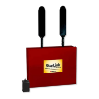
StarLink
™
SLE-LTEVI-FIRE Commercial Series Dual-Path Alarm Communicator -- Installation Instructions 3
any) at the premises requires standby power, there-
fore a UL 1481 / UL 864 or UL Listed ITE UPS must
be used at the premises to power these devices for
a minimum of 24 hours.
TB19: N/O OUT1: Normally open. Dry contact Form C
relay. Add shunt to lower two pins of JP1 for wet
contacts.
TB20: C OUT1: Common. Dry contact Form C relay.
Add shunt to lower two pins of JP1 for wet contacts
(connects relay Common to system ground). Relay
rated 30V AC/DC, 500mA.
TB21: N/C OUT1: Normally closed. Dry contact Form
C relay. Add shunt to lower two pins of JP1 for wet
contacts.
TB22: N/O OUT2: Normally open. Dry contact Form C
relay.
TB23: C OUT2: Common. Dry contact Form C relay.
Relay rated 30V AC/DC, 500mA.
TB24: N/C OUT2: Normally closed. Dry contact Form
C relay.
LED DESCRIPTIONS
The PC board contains several LED's, as follows:
GREEN RF SIGNAL STRENGTH LED
Labeled "D3", this LED is located at the lower right cor-
ner of the PC board.
Every 30 seconds, the StarLink radio receiver section
turns on and listens to the cell tower. Depending on the
signal strength detected, it will blink the Signal Strength
LED from 1 to 8 times, providing a signal strength indica-
tor that is updated constantly and is always displayed.
Refer to Coverage Table below.
Green LED Operation
Signal strength (as received by the radio) is displayed by
this LED blinking 1 to 8 times at a constant rate (with a
short delay between blink cycles). Acceptable power
level is greater than or equal to -91dBm (minimum 4
blinks at the mounting location).
YELLOW OPERATIONAL STATUS LED
Labeled "D4", this LED is located at the bottom right of
the PC board. Operation is as follows:
Normal Standby Condition:
Blinks on momentarily every 10 seconds: Unit is in
standby waiting for an alarm to report.
Processing Alarm Conditions:
When processing an alarm, this LED will blink variably
during each part of the process (dialing, handshaking,
data transmission, etc.).
GREEN RF SIGNAL STRENGTH LED
RADIO RECEIVER COVERAGE TABLE
LED Blinks 8 7 6 5 4 3 2 1
-55 -65 -75 -85 -91 -95 -99 -105
Power
(dBm)
LED LOCATIONS
D4
D3 D5
RED DIAGNOSTIC LED (Labeled "D7")
YELLOW OPERATIONAL STATUS LED (Labeled "D4")
GREEN RF SIGNAL STRENGTH LED (Labeled "D3")
RED TROUBLE LED (Labeled "D5")
FIRE PROGRAMMING OPTION
PERMITTED IN
UL864? (Y/N)
AVAILABLE SETTINGS REQUIRED UL 864 SETTINGS
Unattended Remote Downloading No Enable / Disable
Disabled (Jumper 1 installed). Also required for Commercial installations. Note:
See page 7 "Configuration Download / Firmware Updates" for jumper instruc-
tions.
IN2, IN3, IN4 and IN5 Unsupervised Yes Supervised / Unsupervised
Unsupervised using conduit within 20 feet of FACP (default). If not using conduit,
install Jumpers 4 and 5 and EOL Resistors.
7 Day Supervision, Radio to NOC No
200 seconds, 5 minutes, 6
minutes, 60 minutes, 6
hours, 7 days
200 seconds, 5 minutes, 60 minutes. 6 Hours permitted in Commercial Fire UL
864 with Dual Path enabled.
Trouble on Radio or IP Path
(Annunciate / Report)
Yes Either Path or Both Paths Either Path (annunciation and report of trouble).
NOTICE TO AUTHORITIES HAVING JURISDICTION, USERS, INSTALLERS,
DEALERS, AND OTHER AFFECTED PARTIES
Wi-Fi Module Yes Enable / Disable May be enabled as a primary reporting path for Fire.

 Loading...