12
-4 +5 +6
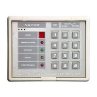
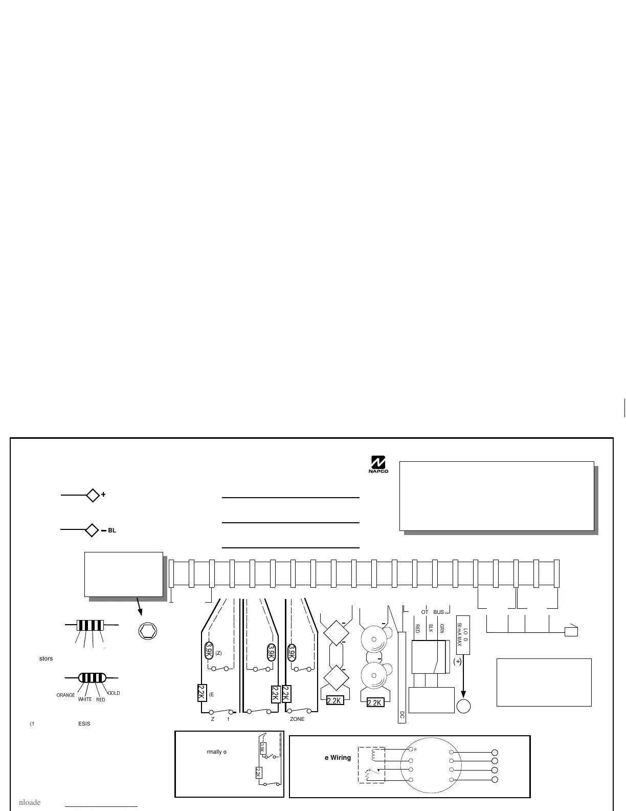
XP-600 Terminals
1 2 +3
GEM-RECV-XP8
16 VAC 20 VA
TRANSFORMER
NAPCO TRF12
(OR EQUIVALENT
SEE WI850A).
Class 2
Transformer.
DO NOT
connect to
switched
outlet.
RED
+
BLACK
E1
E2
RECHARGEABLE
BATTERY
12 VDC 4AH OR 7AH
This equipment should be installed in accordance with Chapter 2
of the National Fire Alarm Code, ANSI/NFPA 72-1993 (National
Fire Protection Association Batterymarch Park, Quincy MA
02269). and local codes. Information describin
proper installa-
tion, operation, testin
, maintenance, evacuation plannin
, and
repair service is to be provided with this equipment. UL Listed
Ener
y Cable is required.
ALL OUTPUTS ARE CURRENT LIMITED
WARNING
TO PREVENT RISK
OF ELECTRIC SHOCK
DISCONNECT TELEPHONE
LINES PRIOR TO SERVICING
EARTH
GROUND
FIRE BELL
Programmable
Output
PGM
(-)
12
+PWR
+10 -11 +12
-13 14 15
16 17 18 19
-7 +8 -9
GND +PWR GND GREEN TIP RING TIP RING
PHONE
(Supervised)
To RJ31X
2.2K EOLR
2.2K EOLR
(SUPERVISED)
(E)
+ +
+
+
COLD WATER GROUND
CONNECTION
USE ONLY COLD-WATER
PIPE OR BURIED GROUND
ROD. USE AT LEAST #16
AWG WIRE.
TELCO
RED
GRN
GRAY
BRN
FIRE
PWR
/2
A
'
P$ 0$;
REMOTE BUS
ZONE 3
(E)
.
(E)
.
ZONE 6
ZONE 5
(Z)
ZONE 1
(E)
.
ZONE 4
(Z)
(E)
5('
%/.
*51
Fire Loop
In
4-Wire Fire Wiring
Power
Out (+)
Power
Out (-)
Power
In (-)
Fire Loop
Out
RED
BLACK
BROWN
BROWN
FT2200
8
7
8
9
Power
In (+)
Fire Power
Ground
Fire Power
Fire
.
.
Normally Open Zone Wiring
Wire the normally open contact
as shown (Zone 4). Program
the zone for
Open Circuit
[06]
operation.
ZONE 2
.
(Z)
ZONE 1
(E)
.
ZONE 4
AUX POWER OUTPUT 10-12.5 VDC
ALL ZONE RESISTORS MUST BE INSTALLED,
EVEN IF ZONE IS NOT USED.
COMBINED STANDBY = KEYPAD CURRENT +
AUX POWER CURRENT + FIRE POWER + PGM
CURRENT.
24 HOUR STANDBY REQUIRES A 7AH BAT-
TERY.
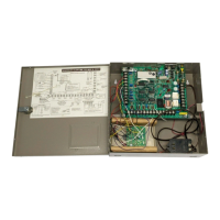
XP-600 WIRING DIAGRAM
(REFER TO INSTALLATION INSTRUCTIONS WI47C)
RESIDENTIAL BURG (4 HOUR STANDBY)
COMBINED STANDBY = 500 mA BELL = 2.0 AMP
RESIDENTIAL FIRE (4 HOUR STANDBY)
(2)
COMBINED STANDBY = 500 mA BELL = 65 mA
RESIDENTIAL FIRE (24 HOUR STANDBY)
(3)
COMBINED STANDBY = 120 mA BELL = 95 mA
(1)
.
.
.
RPX-6
GOLD
RED RED
RED
2.2K
(E)
(Z)
*2/'
:+,7(
5('
3.9K
25$1*(
EZ
Zone
Doubling
TM
Resistors
Wi847c
page 12
Tuesday, September 16, 1997 08:35
 Loading...