4
installation manual
Fig.3-6
Never hold the inlet of the outdoor unit to prevent it from
deforming.
Do not touch the fan with hands or other objects.
Do not lean it more than 45, and do not lay it sidelong.
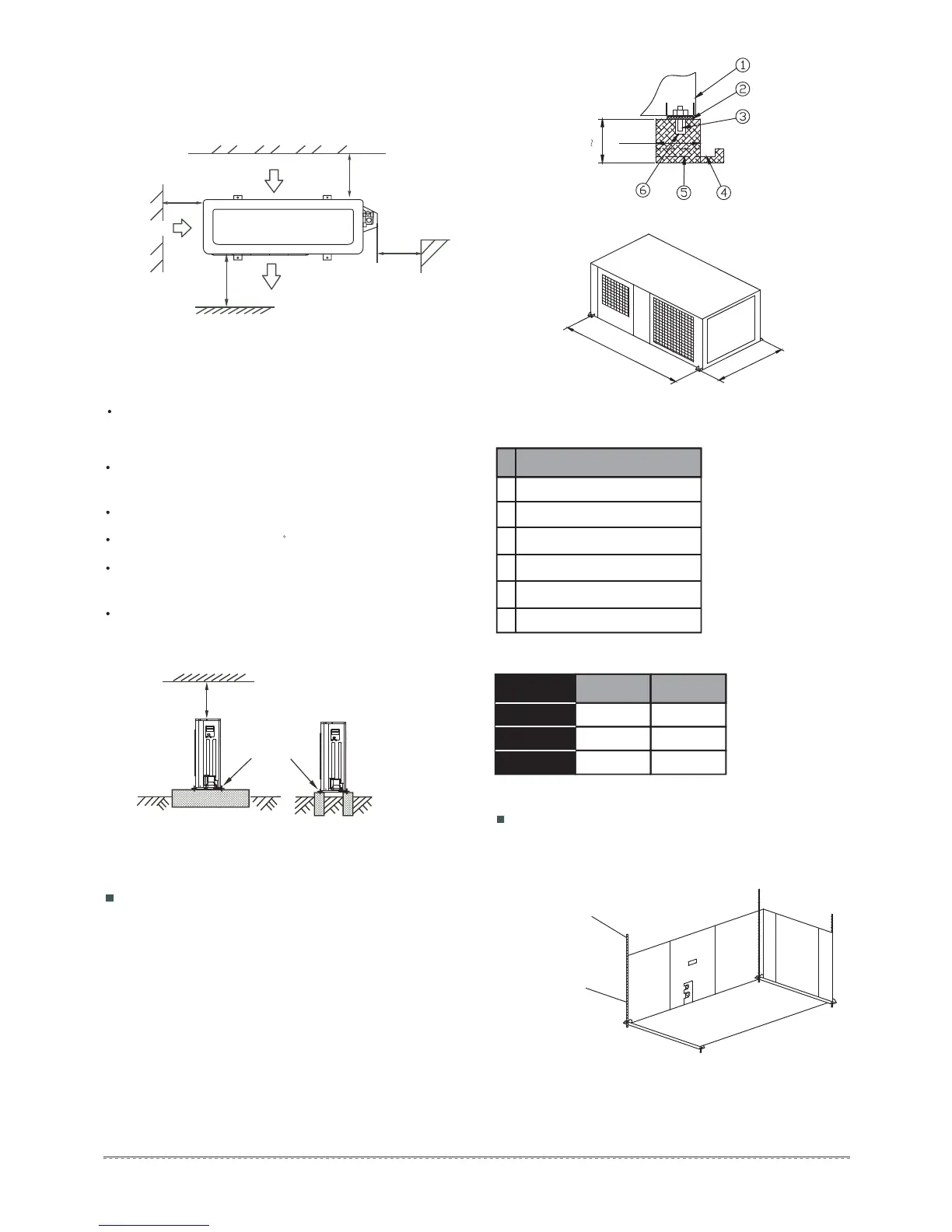
Make concrete foundation accoding to the sepecif-ications of
the outdoor units.(Refer to Fig.6-12)
Fasten the feet of this unit with bolts firmly to prevent it from
collapsing in case of earthquake or strong wind.(Refer to
Fig.6-12)
3.3 Moving and installation
Since the gravity center of the unit is not at its physical
center, so please be careful when lifting it with a sling.
>
6 0
c
m
Fix with bolt
>300mm
m
m
0
0
3 >
m
m
0
0
0
2
>
>600mm
(Wall or obstacle)
Maintain channel
Air outlet
Air inlet
M
P
Air inlet
N
Fig.3-5
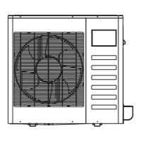
1. Split type outdoor unit
3.2 Space of installation and maintenance
Foundation could be on flat and is recommended be 100-300mm
higher than ground level.
Install a drainage around foundation for smooth drain
When installing the outdoor unit fix the unit by anchor bolts of
M10.
When installing the unit on a roof or a veranda,drain water
sometimes turns to ice on a cold morning. Therefore, avoid
draining in an area that people often use because it is slippery.
1
2
3
4
Concrete Foundation
1. Suspend the unit as the drawing indicates.
2. Ensure that ceiling can resist the Outdoor unit weight indicated
in specification label plate.
Suspended unit
No Description
1 Outdoor Unit
2 Vibration-proof rubber
3 Anchor Bolt M10
4 Drainage (Wide 100×Depth 150)
5 Drainage
6 Mortar Hole (Φ100×Depth 150)
Sling Bolt
Suspension Bracket
Table 3-2
Table 3-3
mm
MODEL
Unit
BC
1120 720
1328 740
1338 820
18~24
30~36
48
Fig.3-7
Fig.3-8
≥100
0
0
1
0
0
3