installation manual
7
CAUTION
CAUTION
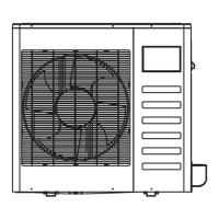
-76 c mHg
Lo-lev er
Hi-leve r
Charg e hos e
Charg e hos e
Vac uum p ump
Lo-lev er
Manifo ld valv e
Multi-m eter
Pressu re meter
Fig.4-7
Additional Refrigerant Charge
4.3
Refrigerant cannot be charged until field wiring has been
completed.
Refrigerant may only be charged after performing the leak
test and the vacuum pumping.
When charging a system, care shall be taken that its
maximum permissible charge is never exceeded, in view of
the danger of liquid hammer.
Charging with an unsuitable substance may cause
explosions and accidents, so always ensure that the
appropriate refrigerant is charged.
Refrigerant containers shall be opened slowly.
Always use protective gloves and protect your eyes when
charging refrigerant.
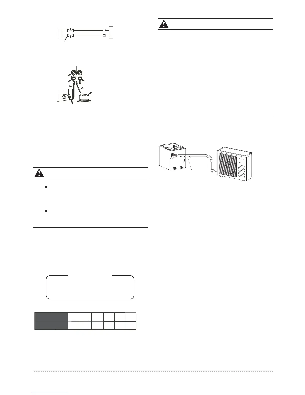
Fig.4-6
Outdoor
unit
Indoor
unit
Stop valv e
Ga s s ide
Liq uid si de
A
C
D
B
Ventilate the air if there was any refrigerant leakage
during the installation.
Leaked refrigerant will generate poisonous gas if
meeting fire.
Make sure there is no refrigerant leakage after the
installation.
Leaked refrigerant will generate poisonous gas if
meeting fire.
Allowed Lenght and Drop of Pipes
Requirements are different when installing the outdoor unit,
please refer to outdoor unit installation manual for detailed
information.
Material and Size of the Pipes
Three length(3m,5m,10m)of pipes are available to purchase.
4.2. Refrigerant pipe installation
The outdoor unit is factory charged with refrigerant. Some
systems require additional charging of refrigerant depending
on pipe lengths. The additional refrigerant to be charged
can be calculated from the following formule:
R = T X (L-5)m
Table 4-4
18 24 36
60
11
30
30
30
MODEL
T (g)
T(
g
): The quantity of the charged
R(g): Additional refrigetant to be charged
L(m): The length of the liquid pipe
refrigerant per meter
30
30
48
30
6. WIRING
The appliance shall be installed in accordance with
national wiring regulations.
The air conditioner should use separate power supply
with rated voltage.
The external power supply to the air conditioner should
have ground wiring, which is linked to the ground wiring
of the indoor and outdoor unit.
The wiring work should be done by qualified persons
according to circuit drawing.
An all-pole disconnection device which has at least 3mm
sepaaration distance in all pole and a residual current
device (RCD) with the rating of above 10mA shall be
incorporated in the fixed wiring according to the national
rule.
Be sure to locate the power wiring and the signal wring
well to avoid cross-disturbance.
Do not turn on the power until you have checked
carefully after wiring.
The power cord type designation is H07RN-F.
5. CONNECTIVE DIAGRAM
Fig. 5-1
Liquid side
orifice
Gas side