Operation & MaintenanceOperation & Maintenance
Layout of Front PanelLayout of Front Panel
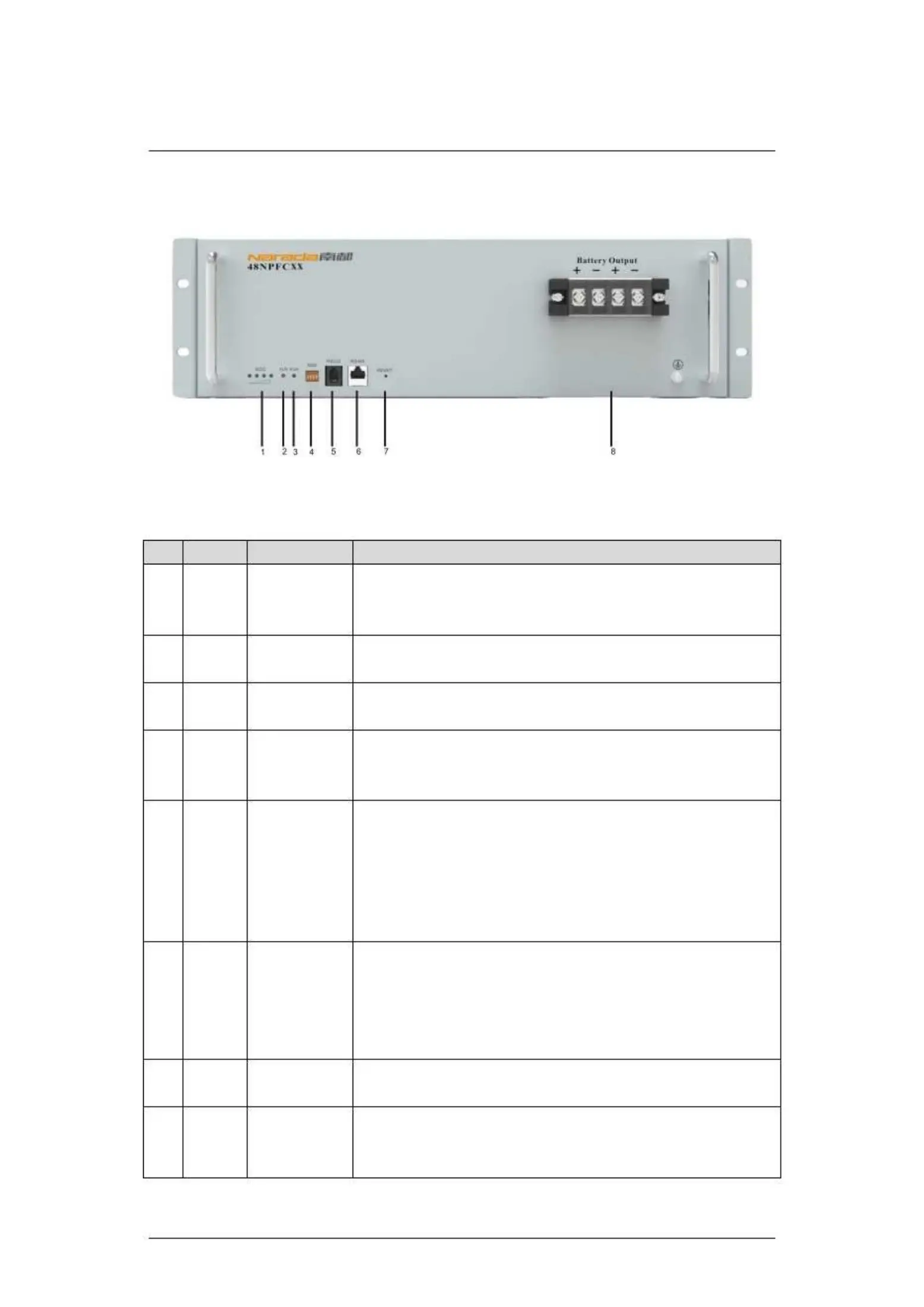
Layout of Front Panel for NPFC Series BatteriesLayout of Front Panel for NPFC Series Batteries
Instruction for Layout of Front PanelInstruction for Layout of Front Panel
Indicators forIndicators for
There are four green LED lights in front panel indicating SOC. SOC isThere are four green LED lights in front panel indicating SOC. SOC is
short for state of charge. Each SOC LED light represents 25% of ratedshort for state of charge. Each SOC LED light represents 25% of rated
capacity. Detailed information is shown incapacity. Detailed information is shown in
Indicator forIndicator for
There is one red LED light in front panel indicating alarms. DetailedThere is one red LED light in front panel indicating alarms. Detailed
information is shown ininformation is shown in
Indicator forIndicator for
running statusrunning status
There is one green LED light in front panel indicating running status.There is one green LED light in front panel indicating running status.
Detailed information is shown inDetailed information is shown in
communicationcommunication
ADD is applicable to modules connected in parallel. ADD consists of fourADD is applicable to modules connected in parallel. ADD consists of four
16pcs (2^4). Detailed information is shown in16pcs (2^4). Detailed information is shown in
communicationcommunication
It is adopting RS-232 series port to upload data. Contents of data transmitIt is adopting RS-232 series port to upload data. Contents of data transmit
include BMS parameters, battery running status, alarms, etc. Generally,include BMS parameters, battery running status, alarms, etc. Generally,
speed rate of RS-232 is 1200bps. RS232 up-link communication can bespeed rate of RS-232 is 1200bps. RS232 up-link communication can be
available for the battery module with a binary communication address ofavailable for the battery module with a binary communication address of
0000 (Master PACK). Protocol for RS232 communication is shown in0000 (Master PACK). Protocol for RS232 communication is shown in
communicationcommunication
It is adopting RS485 series port communication pattern to upload data.It is adopting RS485 series port communication pattern to upload data.
Communication of modules connected in parallel (Slave PACKs) isCommunication of modules connected in parallel (Slave PACKs) is
available through RS 485. Data of slave PACKs will be transmitted toavailable through RS 485. Data of slave PACKs will be transmitted to
Master PACK. Protocol for RS232 communication is shown inMaster PACK. Protocol for RS232 communication is shown in
Press RESET button when abnormity occurs to assure stability of batteryPress RESET button when abnormity occurs to assure stability of battery
Terminals forTerminals for
Using terminals with four cores. Polarities are +, -, +, - from left to right.Using terminals with four cores. Polarities are +, -, +, - from left to right.
The two ‘+’ and ‘The two ‘+’ and ‘
’ are equal relatively. Detailed information is shown in’ are equal relatively. Detailed information is shown in
 Loading...