Chapter 4 VME-MXI-2 Configuration and Installation
© National Instruments Corporation 4-5 PCI-MXI-2 for Linux
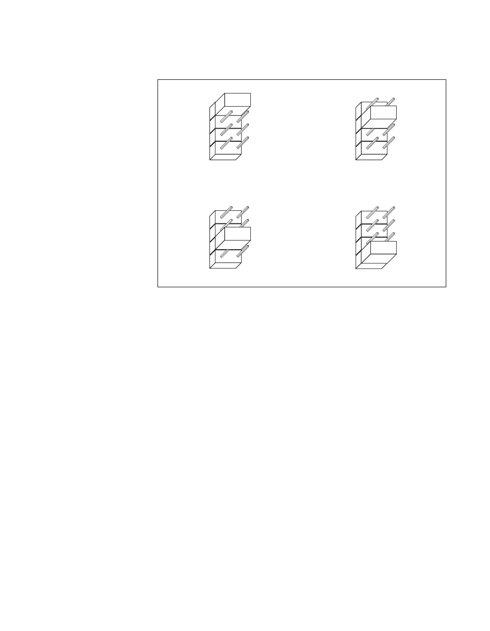
Figure 4-3 shows the four intermodule signaling settings.
Figure 4-3. VME-MXI-2 Intermodule Signaling Settings
MXIbus Termination
The first and last MXIbus devices connected to the MXIbus—whether it is
a single MXI-2 cable or daisy-chained MXI-2 cables—must terminate the
MXIbus. Any MXIbus devices in the middle of a MXIbus daisy chain must
not terminate the MXIbus.
The VME-MXI-2 automatically senses if it is at either end of the MXIbus
cable to terminate the MXIbus. You can manually control MXIbus
termination by defeating the automatic circuitry. Use switches 3 and 4 of
the four-position switch at location U21 to control whether MXIbus
termination is automatic (Figure 4-4a), on (Figure 4-4b), or off
(Figure 4-4c). The settings of switches 1 and 2 have no effect on MXIbus
termination.
Use switch 3 to select whether you want the VME-MXI-2 to automatically
control termination of the MXIbus. Switch 4 lets you manually control
whether to terminate the MXIbus when automatic termination is turned off.
Switch 4 has no effect when switch 3 is set for automatic MXIbus
termination; you must turn off automatic termination if you want to
manually control termination.
a. User-Defined Pin A5 Selected
W2
A5
C5
C30
NC
b. User-Defined Pin C5 Selected
W2
A5
C5
C30
NC
c. User-Defined Pin C30 Selected
W2
A5
C5
C30
NC
d. No User-Defined Pin Selected (Default)
W2
A5
C5
C30
NC
 Loading...