Chapter 8 PFI
M Series User Manual 8-4 ni.com
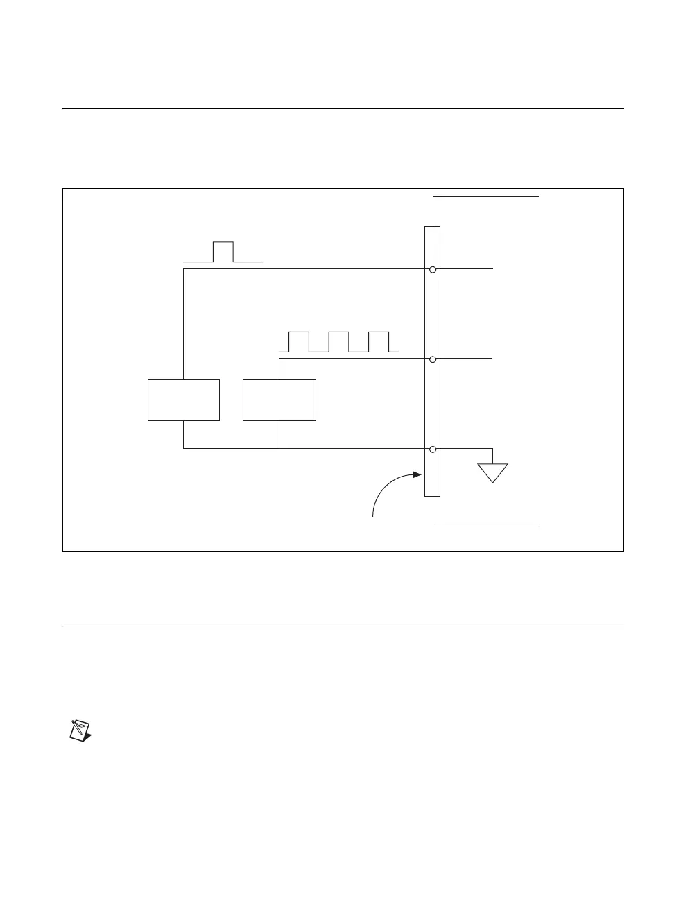
Connecting PFI Input Signals
All PFI input connections are referenced to D GND. Figure 8-2 shows this
reference, and how to connect an external PFI 0 source and an external
PFI 2 source to two PFI terminals.
Figure 8-2. PFI Input Signals Connections
PFI Filters
You can enable a programmable debouncing filter on each PFI, RTSI, or
PXI_STAR signal. When the filters are enabled, your device samples the
input on each rising edge of a filter clock. M Series devices use an onboard
oscillator to generate the filter clock with a 40 MHz frequency.
Note NI-DAQmx only supports filters on counter inputs.
The following is an example of low to high transitions of the input signal.
High to low transitions work similarly.
PFI 0
Source
PFI 2
Source
M Series Device
D GND
PFI 2
PFI 0
I/O Connector
 Loading...