Chapter 2 Device Overview
© National Instruments Corporation 2-3 NI 660x User Manual
are using one of the internal timebases. A counter is using maximum
timebase as its source if the synchronous counting mode is enabled for
that counter.
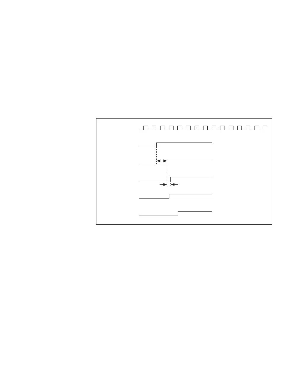
Figures 2-2 and 2-3 illustrate how pad synchronization can be useful.
These figures assume a 1.5 and a 1.75 SOURCE cycle delay between the
PFI 38 input pin, and CTR 0 GATE and CTR 1 GATE, respectively. These
delay values are exaggerated and are used for illustrative purposes.
Figure 2-2 shows counter 0 at the gate edge on PFI 38 one source period
before counter 1. Figure 2-3 shows both counters at the gate edge on PFI 38
at the same time.
Figure 2-2. Counter 0 at Gate Edge on PFI 38 One Source Period before Counter 1
Counter
Source
PFI 38
at CTR 0 GATE
PFI 38
at CTR 1 GATE
Synchronized
GATE at Ctr0
Synchronized
GATE at Ctr1
1 1/2 Cycles
1/4 Cycle
PFI 38
at Input To ASIC
 Loading...