Chapter 3 Signal Connections
© National Instruments Corporation 3-21 NI 660x User Manual
Inductive Effects
For high-speed signals, inductive effects can degrade signal integrity and
cause ringing. To minimize inductive effects, you must minimize ground
loops and allow a return path for currents. Twist your signal with a ground
wire when you connect it to the 68-pin connector block you are using.
Connect the signal wire to the PFI pin you are using and connect the ground
wire to the adjacent D GND line with which the PFI line is twisted.
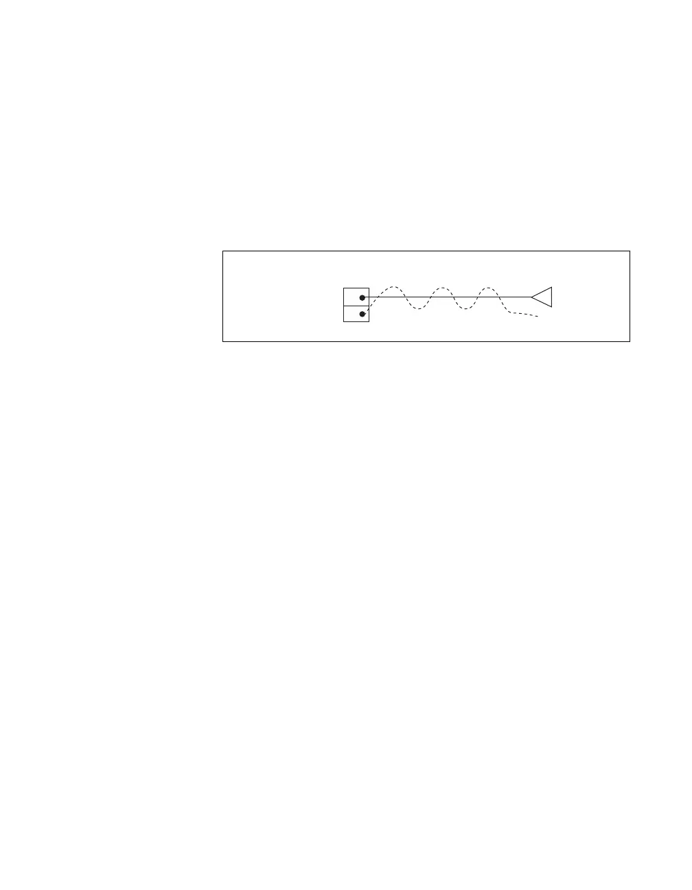
Figure 3-10 shows an example of wiring that minimizes inductive effects.
Figure 3-10. Example of Wiring That Minimizes Inductive Effects
The SH68-68-D1 cable is designed to help minimize inductive effects.
Each signal line is twisted with a ground wire connected to a nearby pin.
Each ground wire is shared by two signal lines.
PFI 39 Pin 2
GND Pin 36
GND
Output of External DeviceSCB-68
 Loading...