© National Instruments Corp. 9 NI 9217 Operating Instructions and Specifications
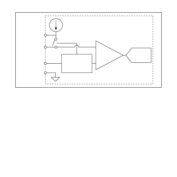
Figure 3. Input Circuitry for One Channel of the NI 9217 in 4-Wire Mode
Each channel has one terminal, RTD+, to which you connect the
positive lead of the RTD signal and one terminal, RTD–, to which
you connect the negative lead of the RTD signal. Each channel also
has a common terminal, COM, and an excitation current source
terminal, EX. You must connect the COM terminal to RTD–. All
four COM terminals are internally connected to the isolated ground
reference of the module. If you are using shielded wiring, connect
one end of the shield to the COM terminal. Refer to Figure 4 for an
illustration of how to connect an RTD to the NI 9217.
NI 9217
ADC
4-Wire EX
COM
RTD+
RTD–
Excitation
Current
Filtered
Amplifier
3-wire & 4-wire
Detection &
Compensation
 Loading...