© National Instruments Corporation 9 NI 6601/6602 Calibration Procedure
Connecting an Alternative Clock Source to the
NI 6601/6602 Device
To connect an alternative clock source to the NI 6601/6602 device,
complete the following steps:
1. Connect the NI 6601/6602 device to a 68-pin breakout box using the
SH68-68-D1 cable.
2. Connect the clock source to pins 7 and 41 of the 68-pin breakout box
using twisted-pair wires.
• Connect the clock to pin 7. Pin 7 corresponds to PFI_35, which is
the SOURCE of counter 1 on all NI 6601/6602 devices.
• Connect the ground of the clock to pin 41, which is digital ground.
Measuring the Frequency of the NI 6601/6602 Device
Note If you are verifying the PXI-6602 on a PXI chassis, the measured frequency is that
of the PXI backplane clock instead of the onboard oscillator. To verify the onboard
oscillator, you must calibrate the PXI-6602 on a PCI chassis using a CompactPCI-to-PCI
adapter.
To measure the frequency of the NI 6601/6602 device for verification,
complete the following steps:
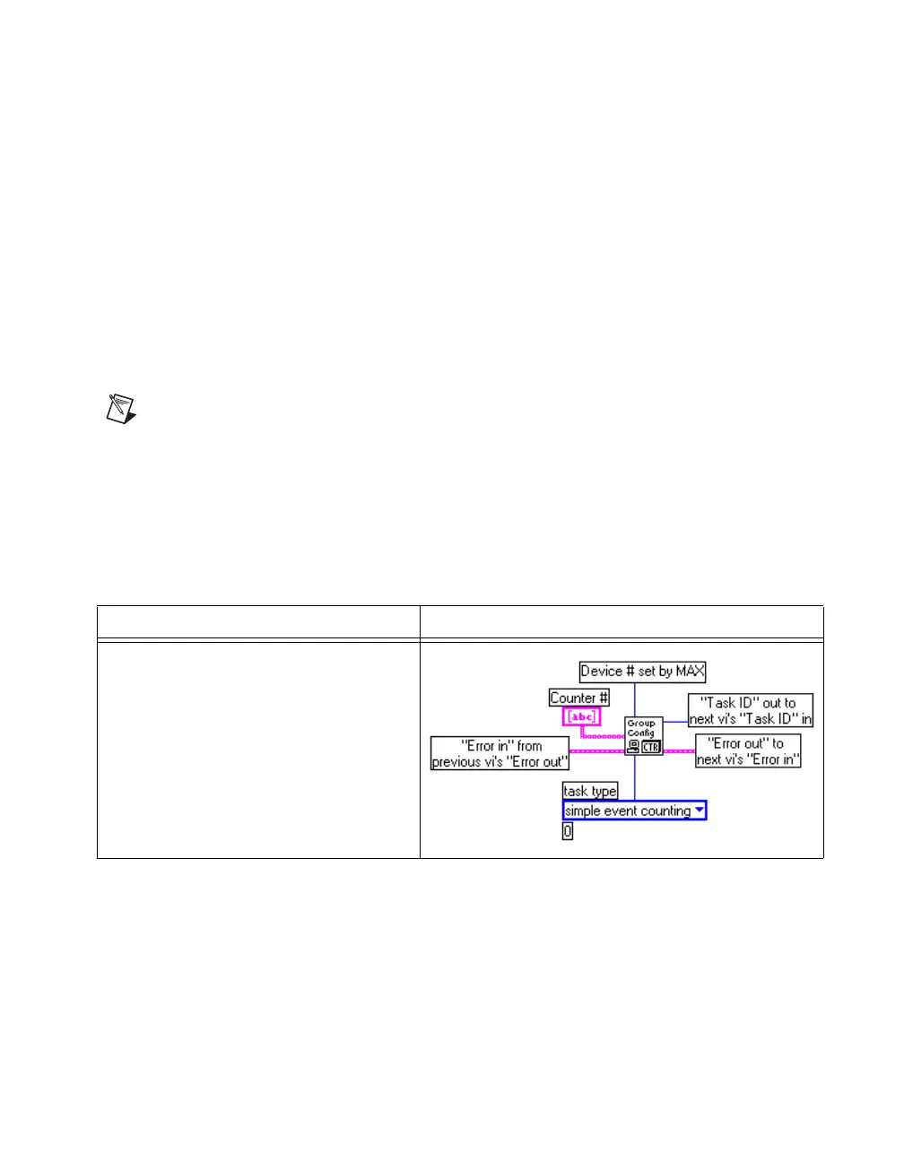
1. Configure counter 0 to perform simple event counting.
Traditional NI-DAQ Function Call LabVIEW Block Diagram
Call GPCTR_Set_Application with the
following parameters:
deviceNumber: The value set by MAX
gpctrNum:
ND_COUNTER_0
application: ND_SIMPLE_EVENT_CNT
 Loading...