NI DC Power Supplies Getting Started Guide 10 ni.com
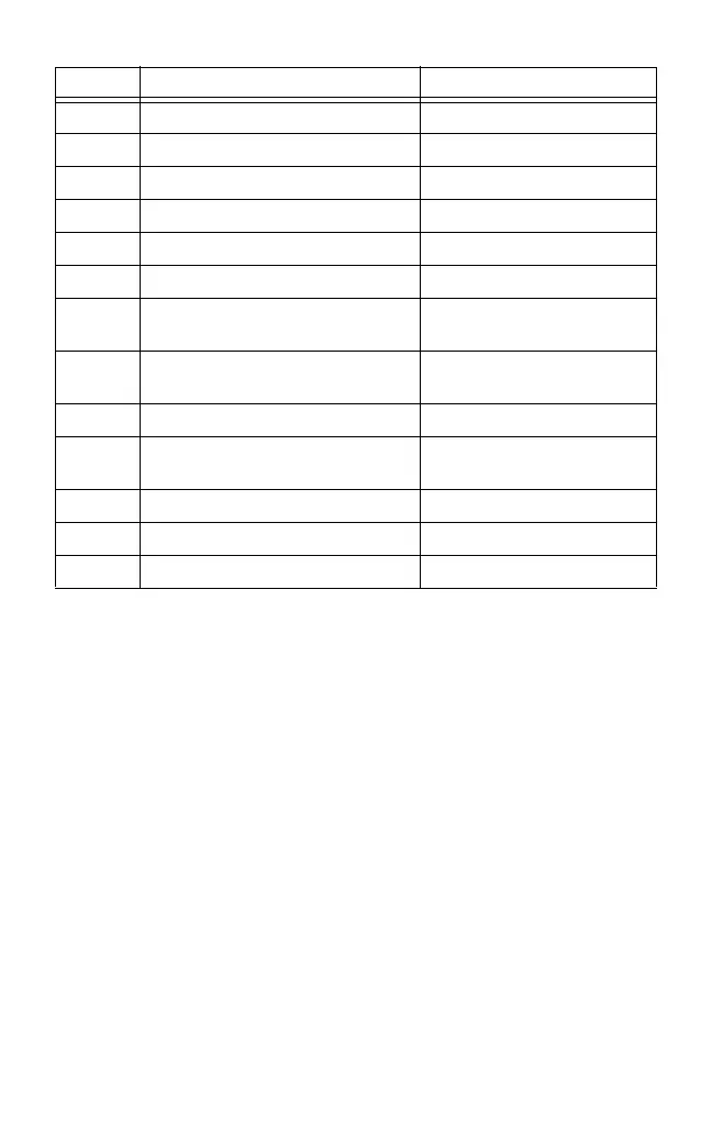
Table 1. NI PXI-4110 Front Panel Connections
Label Item Description
A Output Connector, Terminal 0 Channel 0 (0 V to +6 V)
B Output Connector, Terminal 1 GND
C Output Connector, Terminal 2 Channel 1 (0 V to +20 V)
D Output Connector, Terminal 3 Common Floating GND
E Output Connector, Terminal 4 Common Floating GND
F Output Connector, Terminal 5 Channel 2 (0 V to –20 V)
G Auxiliary Power Input Connector,
Terminal 0
Auxiliary power input
(+11 V to +15.5 V)
H Auxiliary Power Input Connector,
Terminal 1
GND
I Auxiliary Power Input Fuse Holder —
J Auxiliary Power Input Status
Indicator
LED
K Channel 2 Status Indicator LED
L Channel 1 Status Indicator LED
M Channel 0 Status Indicator LED
 Loading...