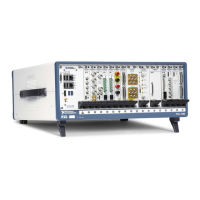
Do you have a question about the National Instruments NI PXIe-1085 and is the answer not in the manual?
| Slots | 18 |
|---|---|
| PXIe Slots | 17 |
| Operating Temperature | 0 °C to 55 °C |
| Chassis Type | PXIe |
| System Slots | 1 |
| Input Voltage Range | 100 V to 240 V |
| Cooling | Forced air |
| PXIe System Timing Slot | 1 |
Highlights the main capabilities and advantages of the NI PXIe-1085 Series chassis.
Details the function and connectivity of the system controller slot.
Description of hybrid slots and compatible module types.
Details the function and connectivity of the system timing slot.
Details the system reference clocks (PXI_CLK10, PXIe_CLK100, PXIe_SYNC100).
Important cautions and warnings regarding safe operation and handling.
Steps for ensuring proper chassis grounding for safety.
Procedure for connecting the chassis to a power source.
General instructions for installing a system controller module.
General instructions for installing peripheral modules into the chassis.
How to configure PXI Express systems using Measurement & Automation Explorer (MAX).
Instructions for configuring trigger lines using MAX.
Steps to reset the chassis' internal circuit breaker.
Procedure for removing and installing the power supply.
Details on AC input, DC output, load regulation, and ripple/noise.
Standards met for information technology equipment safety.
EMC standards compliance for the chassis.
Pin assignments for connectors in the system controller slot.