1-10 | ni.com
Chapter 1 Getting Started
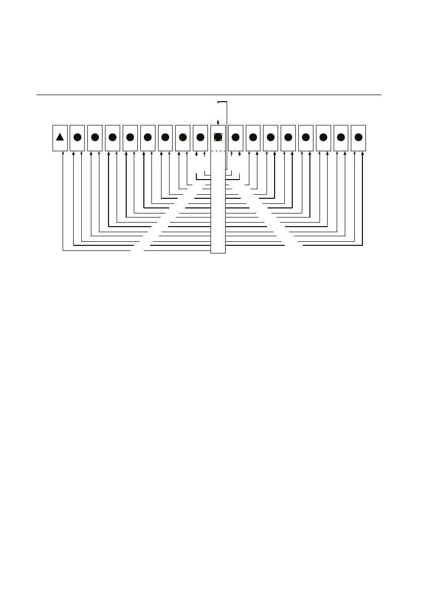
The system timing slot has a pin (PXIe_SYNC_CTRL) through which a system timing module
can control the PXIe_SYNC100 timing. Refer to the PXI Express Specification and the
PXIe_SYNC_CTRL section of this chapter for details.
Figure 1-5. PXI Express Star Connectivity Diagram
PXI Local Bus
The PXI backplane local bus is a daisy-chained bus that connects each peripheral slot with
adjacent peripheral slots to the left and right, as shown in Figure 1-6.
The backplane routes PXI Local Bus 6 between all slots. The left local bus 6 from slot 1 is not
routed anywhere and the right local bus signals from slot 18 are not routed anywhere.
Local bus signals may range from high-speed TTL signals to analog signals as high as 42 V.
Initialization software uses the configuration information specific to each adjacent peripheral
module to evaluate local bus compatibility.
PXI Trigger Bus
All slots on the same PXI bus segment share eight PXI trigger lines. You can use these trigger
lines in a variety of ways. For example, you can use triggers to synchronize the operation of
several different PXI peripheral modules. In other applications, one module located in the
system timing slot can control carefully timed sequences of operations performed on other
modules in the system. Modules can pass triggers to one another, allowing precisely timed
responses to asynchronous external events the system is monitoring or controlling.
The PXI trigger lines from adjacent PXI trigger bus segments can be routed in either direction
across the PXI trigger bridges through buffers. This allows you to send trigger signals to, and
receive trigger signals from, every slot in the chassis. Static trigger routing (user-specified line
and directional assignments) can be configured through Measurement & Automation Explorer
1 2
H
3
H
4
H
5
H
6
H
7
H
8
H
9
H
10
11
H
12
H
13
H
14
H
15
H
16
H
17
H
18
H
DSTAR 6
DSTAR
5
DSTAR
7
DSTAR 4
DSTAR 3
DSTAR 2
DSTAR
1
DSTAR
15
DSTAR
14
DSTAR
13
DSTAR 16
DSTAR 12
DSTAR 11
DSTAR 10
STAR 7
STAR
8
STAR
6
STAR
5
STAR
4
STAR 3
STAR
2
STAR 1 STAR 10
STAR 11
STAR
12
STAR 13
STAR
14
STAR 15
STAR 16
DSTAR 8
DSTA
R 9
DS
TAR 0
ST
AR 9
STAR
0

 Loading...

