2-14 | ni.com
Chapter 2 Installation and Configuration
If the voltages fall within the specified ranges, the chassis complies with the CompactPCI
voltage-limit specifications.
Inhibit Mode Switch
On the rear panel of the chassis there is an Inhibit Mode switch. Refer to Figure 1-2, Rear View
of the NI PXIe-1085 Series Chassis, for the location.
The Inhibit Mode switch should be in the Default position when normal power inhibit switch
functionality is desired. If the user needs to power on a chassis without a system controller
installed the switch should be in the Manual position.
When the Inhibit Mode switch is set to the Manual position, the power supplies are enabled, and
you can use the Inhibit signal (active low) on pin 1 of the Remote Inhibit and Voltage Monitoring
connector to power off the chassis. To remotely power off the chassis, connect the Inhibit pin
(pin 1) to a Logic Ground pin (pin 3 or 8). As long as this connection exists, the chassis will
remain off (standby); when you remove this connection, the chassis turns on.
Note For the Remote Inhibit signal to control the On/Off (standby) state of the
chassis, the Inhibit Mode switch must be in the Manual position.
PXI_CLK10 Front Panel Connectors
There are two SMA connectors on the front of the NI PXIe-1085 Series chassis for PXI_CLK10.
The connectors are labeled IN and OUT. You can use them for supplying the backplane with
PXI_CLK10 or routing the backplane’s PXI_CLK10 to another chassis. Refer to the System
Reference Clock section of Chapter 1, Getting Started, for details about these signals.
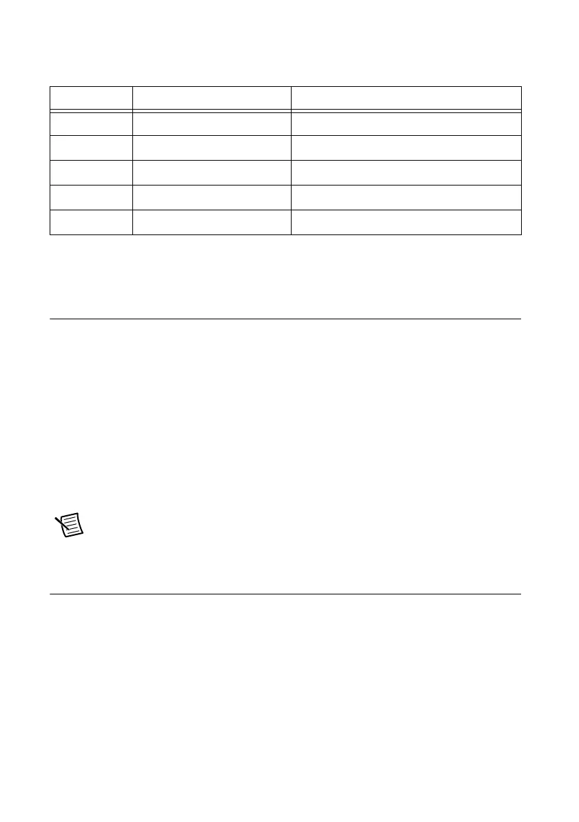
Table 2-5. Power Supply Voltages at Voltage Monitoring Connector
Pin Supply Acceptable Voltage Range
4 +5 V 4.75 to 5.25 V
5 +3.3 V 3.135 to 3.465 V
6 +12 V 11.4 to 12.6 V
7 -12 V -12.6 to -11.4 V
3, 8 Logic Ground 0 V

 Loading...

